58
AUTOMATION AND CONTROL SYSTEM FOR UNITS EVO-T; EVO-T COMPACT
OPERATION AND MAINTENANCE MANUAL
2. EXECUTION STANDARD
2.1 Characteristics of the standard EVO-T and EVO-T COMPACT
control system:
• Wall-mounted Danfoss inverters installed near EVO-T
control cabinet
• Plastic EVO-T control cabinet, IP40-rated – internal version
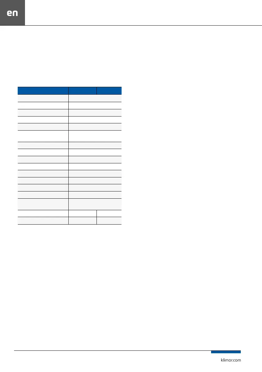
Table no. 1 Electric Parameters of EVO-T (COMPACT)Control Cabinets
NAME „2S” „4S”
Rated voltage (Un) 400V, 50Hz
Insulation rated voltage (Ui) 500V
Rated surge with stand voltage (Uimp) 4kV
Assembly rated current (InA) Chapter 13
Circuit rated current (InC) Chapter 13
Rated short-duration with stand
current (Icw)
1,5 kA
Coordination of short-circuit protections Chapter 13
Rated frequency (fn) 50Hz
Type of the grounding system TN-S
Version internal
Protection class IP 40
EMC classication Environment 2 [class A]
External impact protection IK05
Contamination level 3
Operating conditions
10°C ÷ +40°C, (daily average 24h<
+35°C)
Dimensions 406x303x98 mm 406x303x98 mm
Weight 3,3 kg 3,6 kg
2.2 EVO-T (COMPACT) Control Cabinet content
• Power supply and control with the Modbus RS485 of the
AC (only in EVO-T) motor inverters or EC motor in EBM
fan motors.
• Power supply and control of the water heating coil circu-
lation pump (1x230VAC).
• The control system’s controller.
• Control of the electric heater (0÷10VDC signal and re-
turn alarm signal), the electric heater has to be equipped
with its own power supply and control system (can be
control the electrical heater through Aout1 as a PWM
amplitude 10VDC, the choice we make in the service
Menu/conguration/electric heater).
• Control of DX cooler (level 1, 2 and 0÷10V DC), the cool-
er has to be equipped with its own power supply and
control system.
• 24 VAC power supply and control of the air supply, air
exhaust, recirculation and cross-ow recovery dampers.
• 24 VAC power supply and control of the water heating
and cooling coils’ valve actuators.
3. FIRST START-UP
In order to start up the system for the rst time:
a) Read this manual and application diagram for a venti-
lation system, where the control system is to be applied.
b) Carry out electrical connections in line with the applica-
tion diagram and guidelines listed in this manual.
c) Check, if the sensors and functional elements (actuators,
inverters, etc.) are connected correctly.
d) Turn on the power supply of the control cabinet and set
the application code in the service menu according to the
application diagram (point 4).
e) Set up the system in the service menu (point 9.4).
f) Deactivate the service mode.
g) Turn on the Modbus RTU controller communication
with the EC EBM fans or inverters of air supply and AC air
exhaust fans (if equipped) (point 10.5).
h) Check if the sensor readings and locations are correct.
i) Check operation of the actuators (using Service menu/
output forcing). While testing please pay attention to free
motion of dampers, full open/close state of the actuators.
j) Set the master sensor in “Settings/Temperatures/Master
sensor” menu (point 9.3).
k) Check if any alarms are triggered. If so, they must be
cleared (point 8.4).
l) Start the system (point 8.1).
m) Check again if any alarms are triggered. If so, they must
be cleared (point 8.4).
n) Choose an appropriate menu language at the controller
Regardless the controller’s factory settings please check
the adjustment of the system in terms of temperature ad-
justment, cooling the electric heater (if equipped).
Selection of temperature controller settings should be
carried out so that the system introduces the corrections
as soon as possible, without over-regulation (decrease
the Kp parameter and/or increase the Ti parameter in
order to slow down the system response).
Appropriate selection of PI controller settings, operat-
ing the AHU in accordance to performance determined
in the AHU specication sheet, appropriate selection
of AHU components (recommended analog control
of each heat/cool exchanger), system operation at a
premise with no sudden temperature changes due to
presence of other equipment generating high amount
of heat/cool, enable stable control of lead temperature
with ±0,1K accuracy.
In order to check current accuracy of temperature control
please go into “Service menu/Lead temperature history”
(where last 15 measurements of lead temperature sensor
with selected time period are stored) as well as the “Devia-
tion” is provided, which determines the max. dierence of
current set temperature and last 15 measurements from
the master temperature sensor.

 Loading...