64
AUTOMATION AND CONTROL SYSTEM FOR UNITS EVO-T; EVO-T COMPACT
OPERATION AND MAINTENANCE MANUAL
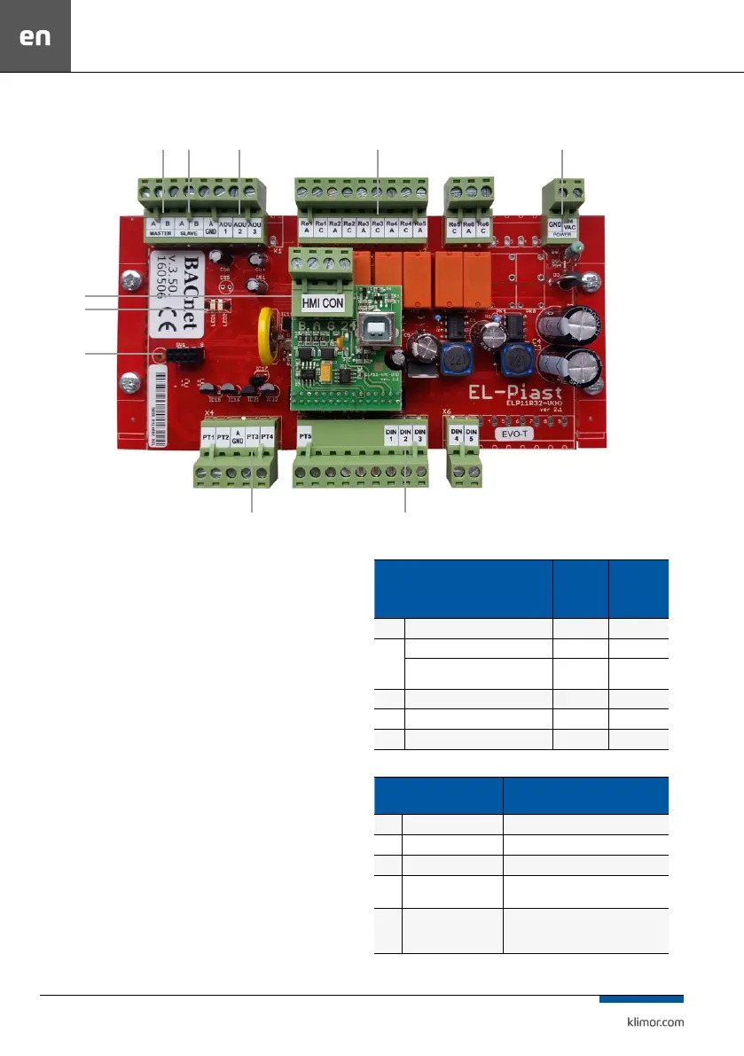
7. DESCRIPTION OF CONTROLLER ELEMENTS
Fig. 2 Connecting elements to the controller
1. RS485 Master output, for communication with BMS
2. RS485 output Slave, for communication with inverters
3. Analog outputs Aou1-3 (0-10VDC)
4. Relay outputs (max 3A, AC1)
5. 24VAC/VDC power supply
6. HMI CON connector, connection with HMI program
-
ming device
7. Communication and alarm messaging
8. ETH connector, here it is possible to install optional
ETH module with RJ45 connector for communication
with BMS
9. Measurement inputs of PT1000 temperature sensors
10. Digital input DIN-5 24VAC supply = state 1
Functions of ETH card:
IP address – Ethernet card address (192.168.0.8)
Network mask – subnet mask (255.255.255.0)
Gateway IP – default gateway (192.168.0.1)
7.1 Standard functions of controller I/Os
Table No. 11 List of digital inputs
Digital inputs (Input NC state – supplying
24VAC to DIN... input switches on the digital
input)
During
correct
system
operation
Lack of re-
quired state
triggers the
alarms
Din 1 Fire alarm system shorted A_AF
Din2
Water heating coil anti-freeze thermostat shorted A_ThHW
Alarm signal of the electric heater
control system
shorted A_ThHE
Din3 Air supply/exhaust lter pressure gauge open A_Filter
Din4 Air supply fan pressure sensor open A_SupPres
Din5 Inverters alarm/conrmation of operation shorted A_VentFC
Table No. 12 List of temperature sensors
PT1000 Temperature sensor
Faulty temperature sensor triggers an
alarm which stops the system
PT1 Air supply A_Tsup
PT2 Air exhaust A_Texh
PT3 External A_Tout
PT4
Air exhaust downstream
heat recovery
A_Trec
PT5
Optional master sensor or
the heater return water
sensor
A_Tmain (when PT5 is selected as a master
sensor)
1
6
7
8
9 10
2 3 4 5
 Loading...