81
300 600
A_ComSupFC
Alarm of no communication with supply inverter 0 – no alarm, 1 – alarm BV
Coil 9600
R
301 602
A_ComSupFC2
Alarm of no communication with supply inverter 2 0 – no alarm, 1 – alarm BV
Coil 9632
R
302 604
A_ComExhFC
Alarm of no communication with exhaust inverter 0 – no alarm, 1 – alarm BV
Coil 9664
R
303 606
A_ComExhFC2
Alarm of no communication with exhaust inverter 2 0 – no alarm, 1 – alarm BV
Coil 9696
R
304 608 A_Tsup Supply temperature sensor alarm 0 – no alarm, 1 – alarm BV
Coil 9728
R
305 610 A_Texh Exhaust temperature sensor alarm 0 – no alarm, 1 – alarm BV
Coil 9760
R
306 612 A_Tout External temperature sensor alarm 0 – no alarm, 1 – alarm BV
Coil 9792
R
307 614 A_Trec Alarm of the exhaust temperature sensor downstream the recuperation 0 – no alarm, 1 – alarm BV
Coil 9824
R
308 616 A_TsupPrim Alarm of the supply temperature sensor downstream the main heater 0 – no alarm, 1 – alarm BV
Coil 9856
R
309 618
A_TbackWater
Alarm of the return water temperature sensor from the water heater 0 – no alarm, 1 – alarm BV
Coil 9888
R
310 620 A_Tmain Master temperature sensor alarm 0 – no alarm, 1 – alarm BV
Coil 9920
R
311 622 A_InEmul Controller input emulation alarm 0 – no alarm, 1 – alarm BV
Coil 9952
R
312 624 A_OutForce Controller output forcing alarm 0 – no alarm, 1 – alarm BV
Coil 9984
R
313 626 Alarm Collective alarm 0 – no alarm, 1 – alarm BV
Coil
10016
R
10.2 Bacnet MS-TP communication with the BMS system
Search for BacNet variables after connecting the
switched on controller and implementing appropriate
BacNet network settings.
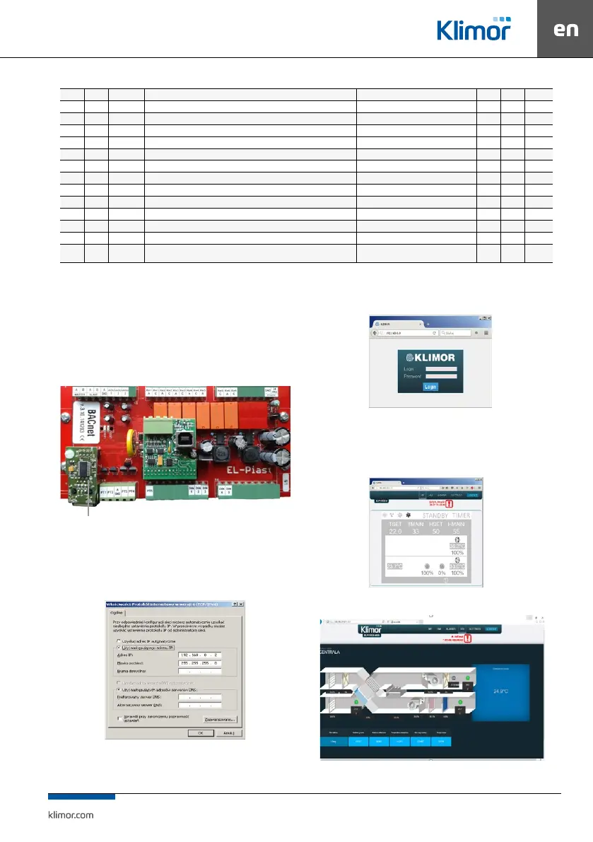
10.3 Control via WWW
The controller can be managed via www protocol.
The shown below optional Ethernet adapter is required
as a hardware element:
Fig. 9 Location for instal ETH module
To connect from a local PC connected directly with
cable with the controller’s ETH adapter:
1. Input the following values in the settings of the PC’s
network adapter for the TCP4 protocol:
Fig. 10 Network module settings of the PC for TCP4 protocol
2. Then open the Internet browser and enter the default
controller address: 192.168.0.8. The window appears
– please enter default login: admin and password: admin
Fig. 11 Login window and access passwords
3. When the login and password are entered and the
login is validated, the controller’s HMI screen appears.
Here you can change the settings and view all control
-
ler menu options.
Fig. 12 Controller HMI graphic screen
Fig. 13 AHU visualisation screen
ETH module with RJ connector