93
13. CABLE CROSS SECTIONS AND PROTECTIONS
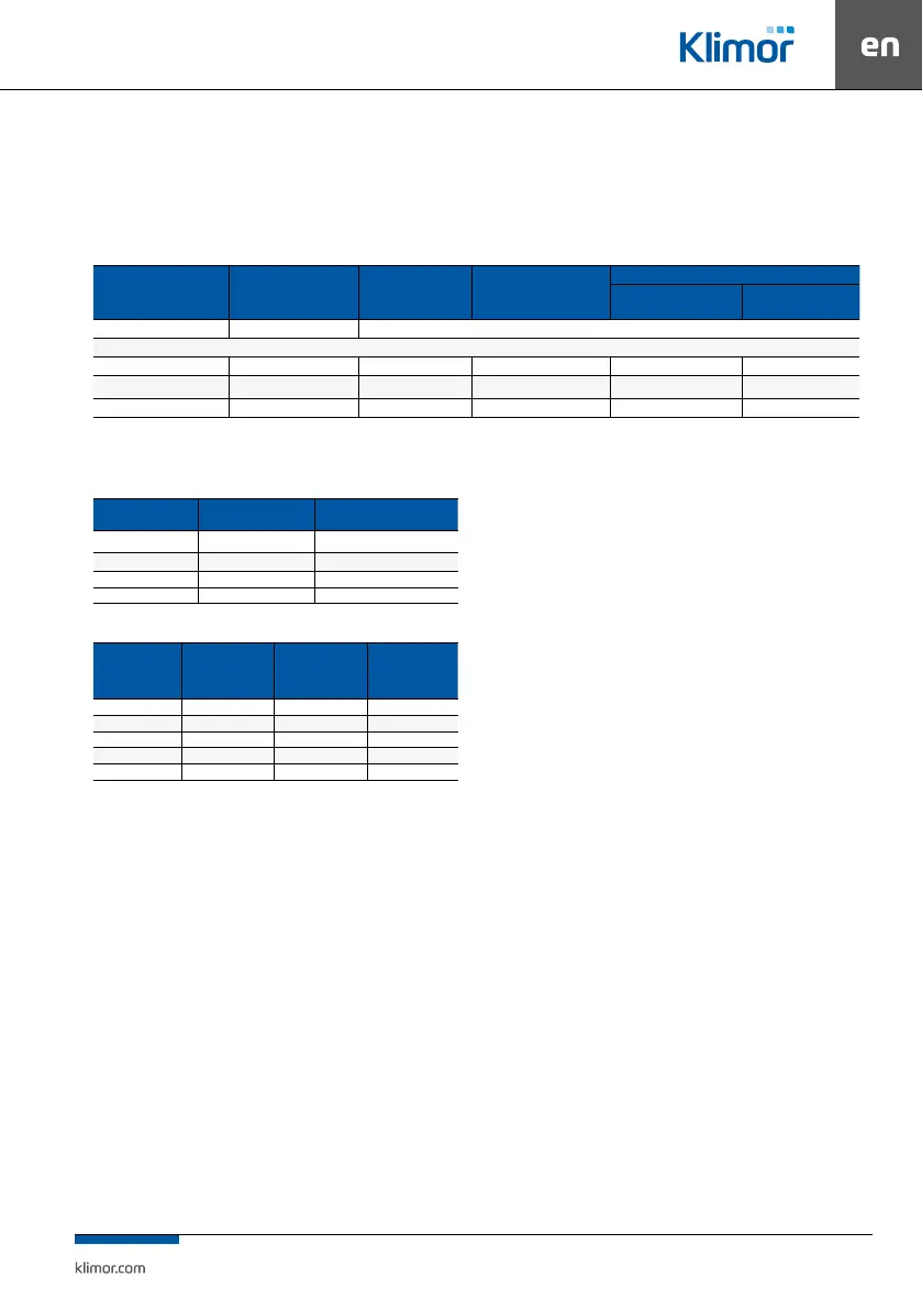
13.1 Cross sections of power cables for fan motors and protection
units
Table no. 28 Cross sections of power cables for fan motors and protection units
RATED MOTOR OUTPUT
PROTECTION OF INVERTER
OR EC FAN
POWER LEAD OF THE
INVERTER OR EC FAN
POWER LEAD OF THE AC FAN
MOTOR
CONTROL CABINET POWER LEAD
CGEVOT 2S
2 MOTORS
CGEVOT 4S
4 MOTORS
[kW] [mm
2
]
3x230/50Hz
EC- 0,50 gG10 3x1,5 - 3x1,5 5x2,5
AC- 0,75 gG20 3x1,5 4x1,5 3x2,5 5x4,0
AC -1,5 gG32 3x2,5 4x1,5 3x2,5 5x4,0
13.2 Cross sections of power leads of electric heater
Table no. 29 Power supply of the EH module
HEATER OUTPUT
ASSEMBLY RATED CURRENT
INA
POWER LEAD OF CONTROL
CABINET
[kW] [A] [mm
2
]
14.4 21 5x6,0
21.6 33 5x6,0
32.4 49 5x10,0
Table no. 30 Power supply of individual stages of the electric heater
HEATER STAGE
OUTPUT
RATED CURRENT
OF ONE STAGE
INC
POWER LEAD OF
ONE STAGE
SELECTION OF
FUSES
kW [InC] [A] [mm
2
] [A]
P ≤ 3,6 5,2 4x1,5 6
3,6 < P≤ 7,2 10,4 4x1,5 12
7,2 < P≤ 10,8 15,7 4x2,5 20
P=14,4 21,0 4x4,0 25
NOTE:
Cable cross-sections apply to PVC insulations selected
according to the standard PN-HD 60365-5-52:2011 for
the installation made according to B2 and for length
up to 10 m (copper conductors, conductor temper-
ature 70°C, ambient temperature 30°C in the air). At
observance of selectivity of protection units, the stat
-
ed cross-sections of cables supplying controllers and
inverters will only be protected against the eects of
short-circuit currents.
The diagram shows max cross sections of leads for
3x12kW.
Individual control wiring diagrams for applications are
attached to this OMM Manual.