83
10.4 Communication of the RS485 Slave, Modbus RTU with Danfoss FC51 inverter
Please see the website below in order to obtain technical documentation of Danfoss inverters.
http://www.danfoss.com/poland/businessareas/drivessolutions/frequency+converters/vlt+micro+drive.htm
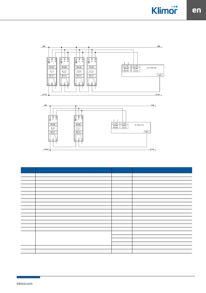
Fig. 18 Example for “EVO-T 4S” system, with double air supply, double air exhaust
Fig. 19 Example for “EVO-T 2S” system, with single air supply, single air exhaust or double air supply only
Table no. 24 Danfoss FC51 inverters conguration, RS485 control
Code Name Set point value Description
1-03 Torque specs. 0 Constant torque
1-20 Rated motor output ...kW Motor rating plate
1-24 Rated motor current ...A Motor rating plate
1-25 Rated motor speed ...rpm Motor rating plate
1-90 Thermal motor protection 4 Emergency ETR only
3-02 Min requested frequency 0.000 Always enter this value
3-03 Max requested frequency Fz max Custom setting
3-17 Source of requested value 3 11 Modbus
4-14 Max. output frequency Fz max Custom setting
4-16 Output current limit 110.0
5-40 Relay function 6 Operation without alarm
8-01 Control location 0 Digital and control word
8-02 Source of control word 1 FC RS485
8-03 Communication latency time 10.0
8-04 Reaction on communication time-out 2 Stop
8-30 Selection of communication protocol 2 Modbus RTU
8-31 Inverter address in Modbus
1 Air supply fan inverter
2 Air supply fan inverter 2
3 Air exhaust fan inverter
4 Air exhaust fan inverter 2
8-32 FC port baud rate 2 9600
8-33 FC port parity 3 No parity, 2 stop bits
NOTE:
Fz max – inverter frequency for operation with max fan air ow (resulted from air distribution system adjustment). Initially enter the
frequency from the AHU technical documentation.