57
1. INTRODUCTION
The Control Cabinet EL-…-…-…-…-… meets the
requirements of: PN-EN 61439-1:2011, PN-EN 61439-
3:2012, PN-EN 61000-6-1:2008, PN-EN 61000-6-3:2008.
You can download certicates from the web page:
www.el-piast.com/download/
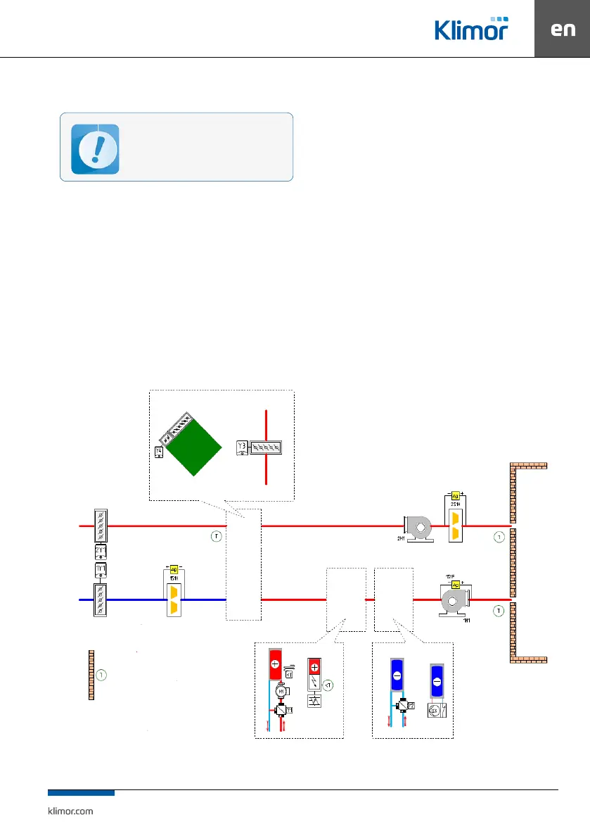
Switch level application:
• Air supply and air supply-exhaust units
• Systems with water heater (pre- and secondary) and
electrical heater (pre- and secondary)
• Systems with water cooler and direct expansion cooler
• Systems with heat recovery based on cross-ow heat
exchanger or mixing chamber
• “2S” Control Cabinets – power supply: 1x230V 50Hz
– designed for EVO-T 4100, 1200, 9200 air supply-ex
-
haust AHUs equipped with fan sections featuring a sin-
gle fan, both AC and EC and EVO-T COMPACT with EC;
and for EVO-T 1200 and 9200 air supply AHUs equipped
with fan sections featuring double fans, (EC in EVO-T
1200 and AC and EC in EVO-T 9200).
“4S” Control Cabinets – power supply: 3x400V 50Hz
– designed for EVO-T 1200, 9200 and COMPACT air
supply-exhaust AHUs equipped with fan sections
featuring double EC fans and for EVO-T 9200 air sup
-
ply-exhaust AHUs equipped with fan sections featur-
ing double AC fans.
Electric heaters equipped with dedicated power supply
unit controlled, start/stop signal control, 0÷10VDC and
return alarm signal (can be control the electrical heater
through Aout1 as a PWM amplitude 10VDC, the choice
we make in the service Menu/conguration/electric
heater).
DX cooling coils equipped with dedicated power sup
-
ply unit controlled, start/stop signal control, 0÷10VDC
or max. two start/stop signals.
The control cabinet may be operated by un-
qualied personnel
Fig. 1 Operation range of control system