71
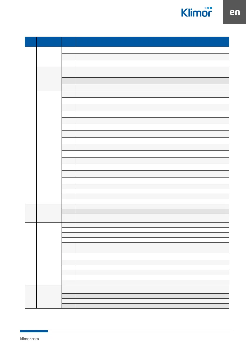
Group Name
Default
value
Description / Settings menu
Fans
-
10 s Switch on delay – time between starting the dampers and starting the fans.
15 s Damper switch o delay – time between stopping the fan and stopping the dampers.
30 s Pressure gauge delay – time from starting the fans after which lter pressure is measured.
Cooling
30 s
Cooling down time – time from switching "Operation in 1st, 2nd, 3rd speed" operation mode into "Stop" operation mode and stopping
operation of the electric heater or/and DX cooler till stopping the fans.
100% Air supply – air supply fans capacity during cooling down
100% Air exhaust – air exhaust fans capacity during cooling down
RS 485
Inactive Air supply inverter RS485 – activation of communication with the air supply fan inverter/ EC controller
Inactive Air supply inverter 2 RS485 – activation of communication with the secondary air supply fan inverter/EC controller
Inactive Air exhaust inverter RS485 – activation of communication with the air exhaust fan inverter/EC controller
Inactive Air exhaust inverter 2 RS485 – activation of communication with the secondary air exhaust fan inverter/EC controller
1 Air supply inverter address – air supply fan inverter/EC controller address
2 Air supply inverter 2 address – secondary air supply fan inverter/EC controller address
3 Air exhaust inverter address – air exhaust fan inverter/EC controller address
4 Air exhaust inverter 2 address – secondary air exhaust fan inverter/EC controller address
70% Min air supply airow – setting of the 1st speed airow
85% Medium air supply airow – setting of the 2nd speed airow
100% Max air supply airow – setting of the 3rd speed airow
70% Min air exhaust airow – setting of the 1st speed airow
85% Medium air exhaust airow – setting of the 2nd speed airow
100% Max air exhaust airow – setting of the 3rd speed airow
60s Acceleration time – inverters start-up time
60s Stopping time – inverters stopping time
0.3s Tcom – time of communication with the inverter
3s Twait – response awaiting time in communication with the inverter
Regulation
adjustment
-
20% Heat recovery adjustment part (editable parameter)
20% Mixing chamber adjustment part (editable parameter)
...% Heater/cooler adjustment part (read-only parameter)
Controllers
1 Kp_grzania – gain of heater controller
60s Ti_grzania – integration constant of heater controller
1 Kp_chłodzenia – gain of cooler controller
60s Ti_chłodzenia – integration constant of cooler controller
Summer/
Winter
PI chłodzenia – possibility to activate the cooling controller only in summer or summer and winter
30s Opóźnienie załączenia – possibility to make a delay switching setting for the cooling controller
1 Kp_nawiewu – gain of air supply controller
45s Ti_nawiewu – integration constant of air supply controller
40°C Tmax – maximum supply temperature (cascade controller)
15°C Tmin – minimum supply temperature (cascade controller)
...°C TsetBlowAct – the current supply setpoint temperature (cascade controller)
Recovery -
450 s
Starting ramp – once the system is started, the 100% heat recovery is started with dropping ramp till current heat recovery actuation
resulting from the adjustment process
2°C Frosting limit – temperate below which the anti-frost function is activated
1 Kp_zwalniania – gain of ant-frost function controller
30s Ti_zwalniania – integration constant of ant-frost function controller