75
Addresses from the table are recalculated for the Mod-
bus protocol in the following way:
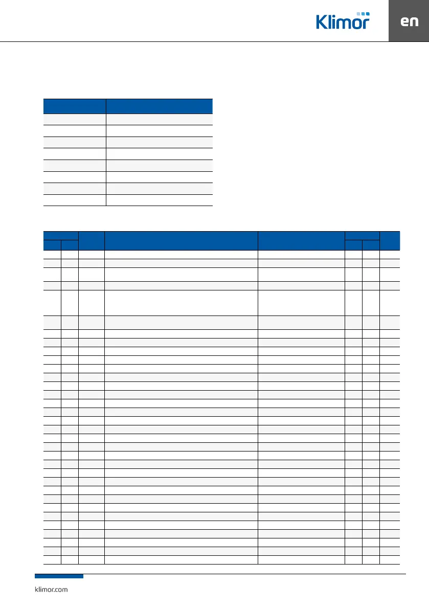
Table no. 19 Recalculating addresses
Address space Address calculation
0x0000 … 0x1000 Modbus Adres = Adr.
0x1000 … 0x2000 Modbus Adres = 0x1000 + Adr.
0x2000 … 0x3000 Modbus Adres = 0x2000 + Adr.
0x3000 … 0x4000 Modbus Adres = 0x3000 + Adr.
0x4000 … 0x5000 Modbus Adres = 0x4000 + (Adr. / 2)
0x5000 … 0x6000 Modbus Adres = 0x5000 + (Adr. / 2)
0x6000 … 0x7000 Modbus Adres = 0x6000 + (Adr. / 2)
0x7000 … 0x8000 Modbus Adres = 0x7000 + (Adr. / 2)
NOTE: you cannot write a single 16-bit register in the
0x1000 … 0x4000 address spaces. In this case you have
to write the registers in pairs using a command: Preset
Multiple Registers (0x10), which is connected with full
value of 32-bit variable. It means that the record start
address and number of registers must be an even value.
Table no. 20 Variables Main menu
DEC address
Variable
name
Description / Variables Main Menu States
Type Read [R]
/Write
[W]
BacNet Modbus BacNet Modbus
0 0 LanguageAct Selected controller menu language 1 – PL, 2 – EN, 4 – RU MSV Register R
1 2 ModeOnOffTP Set work mode (for main screen Type 4) – touch screen 0 – stop, 1 – start MSV Register R
2 4
ModeStdCal-
LevelTP
Set work mode (for main screen Type 4) – touch screen 0 – manual, 1 – standby, 2 – timer MSV Register R/W
3 6 SetLevelTP Manual mode level setting (for main screen Type 4) – touch screen 1 = 1 AV Register R/W
4 8 UnitState System state (current)
0 – stop, 1 – work, level 1, 2 – work, level 2,
4 – work, level 3, 8 – primary heating,
16 – cooling, 32 – heating, 64 – blocking alarm,
128 – maintenance mode
MSV Register R/W
5 10 WorkMode1 Set work mode (for main screen Type 1)
0 – stop, 1 – speed 1, 2 – speed 2, 4 – speed
3, 8 – standby, 16 – timer
MSV Register R/W
6 12 WorkMode2 Set work mode (for main screen Type 2) 1°C = 256 (22°C = 22*256 = 5632 = 0x1600) MSV Register R/W
7 14 WorkMode3 Set work mode (for main screen Type 3) 1°C = 256 (22°C = 22*256 = 5632 = 0x1600) MSV Register R
8 16 WorkMode4 Set work mode (for main screen Type 4) 1°C = 256 (22°C = 22*256 = 5632 = 0x1600) MSV Register R
9 18 Tset Temperature setting 1°C = 256 (22°C = 22*256 = 5632 = 0x1600) AV Register R
10 20 TsetActual Set point (taking account of the calendar and the start ramp) 1°C = 256 (22°C = 22*256 = 5632 = 0x1600) AV Register R
11 22 Tmain Temperature control master sensor temperature 1°C = 256 (22°C = 22*256 = 5632 = 0x1600) AV Register R
12 24 B1 Supply temperature 1°C = 256 (22°C = 22*256 = 5632 = 0x1600) AV Register R
13 26 B2 Exhaust temperature 1°C = 256 (22°C = 22*256 = 5632 = 0x1600) AV Register R
14 28 B3 Exhaust temperature 0 – stop, 1 – start AV Register R
15 30 B4 Exhaust temperature down-stream the recuperation (optional) 1% = 256 (22% = 22*256 = 5632 = 0x1600) AV Register R
16 32 B5 Optional master temperature or temperature downstream the main heater 1% = 256 (22% = 22*256 = 5632 = 0x1600) AV Register R
17 34 B8 Return water temperature from water heater 1A = 256 (22A = 22*256 = 5632 = 0x1600) AV Register R
18 36 Vent Start/stop signal of unit fans 1Hz = 256 (22Hz = 22*256 = 5632 = 0x1600) MSV Coil 576 R
19 38 PwrSup Supply inverter control 1%= 256 (22% = 22*256 = 5632 = 0x1600) AV Register R
20 40 PwrExh Exhaust inverter control 1% = 256 (22% = 22*256 = 5632 = 0x1600) AV Register R
21 42 Isup Supply fan motor current 1A = 256 (22A = 22*256 = 5632 = 0x1600) AV Register R
22 44 Fsup RS485: Supply fan inverter frequency 1Hz = 256 (22Hz = 22*256 = 5632 = 0x1600) AV Register R
23 46 RPMsup RS485: Supply fan EC motor revolutions 1rpm=256(22rpm = 22*256 = 5632 = 0x1600) AV Register R
24 48 Usup RS485: Inverter output voltage or DV voltage of supply fan EC motor 1V = 256 (22V = 22*256 = 5632 = 0x1600) AV Register R
25 50 FaultSup RS485: Supply fan inverter of EC motor alarm code 1A = 1A (HEX) www.el-piast.com/alarms-decoder AV Register R
26 52 ComSup RS485: Correctness of Modbus communication of ELP controller with supply fan inverter 1% = 256 (22% = 22*256 = 5632 = 0x1600) AV Register R
27 54 Isup2 RS485: Supply fan 2 motor current 1A = 256 (22A = 22*256 = 5632 = 0x1600) AV Register R
28 56 Fsup2 RS485: Supply fan 2 inverter frequency 1Hz = 256 (22Hz = 22*256 = 5632 = 0x1600) AV Register R
29 58 RPMsup2 RS485: Supply fan 2 EC motor revolutions 1rpm=256(22rpm = 22*256 = 5632 = 0x1600) AV Register R
30 60 Usup2 RS485: Inverter output voltage or DV voltage of supply fan 2 EC motor 1V = 256 (22V = 22*256 = 5632 = 0x1600) AV Register R
31 62 FaultSup2 RS485: Supply fan 2 inverter of EC motor alarm code 1A = 1A (HEX) www.el-piast.com/alarms-decoder AV Register R
32 64 ComSup2 RS485: Correctness of Modbus communication of ELP controller with supply fan 2 inverter 1% = 256 (22% = 22*256 = 5632 = 0x1600) AV Register R