2 Specification
© Copyright Reserved KONICS Co., Ltd. 23
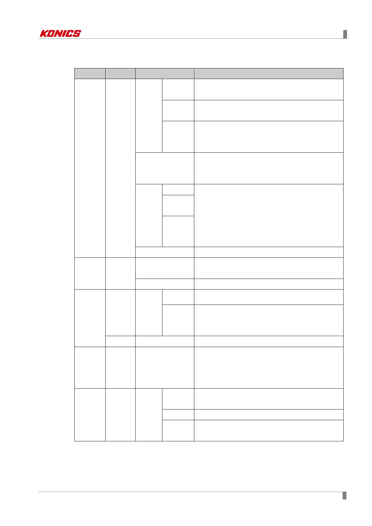
2.2 I/O card
Universal
input card
KRN-UI2
Input
specific
ation
※
1
RTD
JPT100Ω, DPT100Ω, DPT50Ω, CU100Ω,
CU50Ω(Supply current 420µA)
Thermoco
uple
B, C(W5), E, G, J, K, L, L(Russia), N, P, R, S, T, U
Analog
Voltage: ±60mV ±200mV ±2V, 1-5V, ±5V, -1V to
10V
Current: 0.00to20.00 ㎃ 4.00to20.00 ㎃
Input impedance
Voltage(V): Min. 150kΩ
RTD, thermocouple, voltage(mV): min. 2MΩ
current: 51Ω
Display
accurac
y
※
2
RTD
Warm-up time: Min. 30 minutes
·Room temperature (25℃±5℃) section: ±0.1% F.S.±
1 Digit
·Out of range of room temperature: ±0.2% F.S.±1 Digit
RTD: 500 to 850℃ is PV value±0.5%±1 Digit
Thermocouple: Below -100℃ is ±0.3% F.S. ±1 Digit
Thermoco
uple
Analog
Resolution 16Bit
Digital
input card
KRN-DI6
Noncontact input
ON: Max. 1V of residual voltage, OFF: Max. 0.1 ㎃
leakage current
Contact input
ON: Max. 1kΩ, OFF: Min. 100kΩ, Short: Approx. 4 ㎃
Alarm
output
card
KRN-AR4
Alarm
relay
output
Capacity
250VAC 3A
30VDC 3A, 1 Form A (resistance load)
Life
Mechanical: Min. 50,000,000 operations
Electrical: Min. 100,000 operations
(3A 250V AC, 3A 30V DC)
KRN-AT6 Alarm TR output
NPN Open Collector, 12-24VDC / 30 ㎃ Max.
Transmitt
er power
output
card
KRN-
24V3
Power output for
transmitter
※
5
24±2VDC, total 3 channel, max. 30 ㎃ per 1 channel
built-in over-current protection circuit
Communi
cation
output
card
※
3
KRN-
COM
Commu
nication
output
RS485
Modbus RTU
※Recommended to use shield cable over AWG24
Ethernet IEEE802.3(U), 10/100 BASE-T(Modbus TCP)
USB
Device
※
4
USB V2.0 Full Speed(Device Control)
※1. To change input specification, you must turn OFF the power of KRN100, remove universal
input card, set inner jumper pin (Please refer to 4.2 I/O card.) and re-connect it.
 Loading...