KW Aufzugstechnik GmbH OPERATING MANUAL DAVID-613
DAVID-D613-V125-E 13.04.2021 Page - 239 -
I04a- Commissioning with CANopen Shaft-Copy KÜBLER ANTS-SAFE
1.0 Making the mechanical Mounting
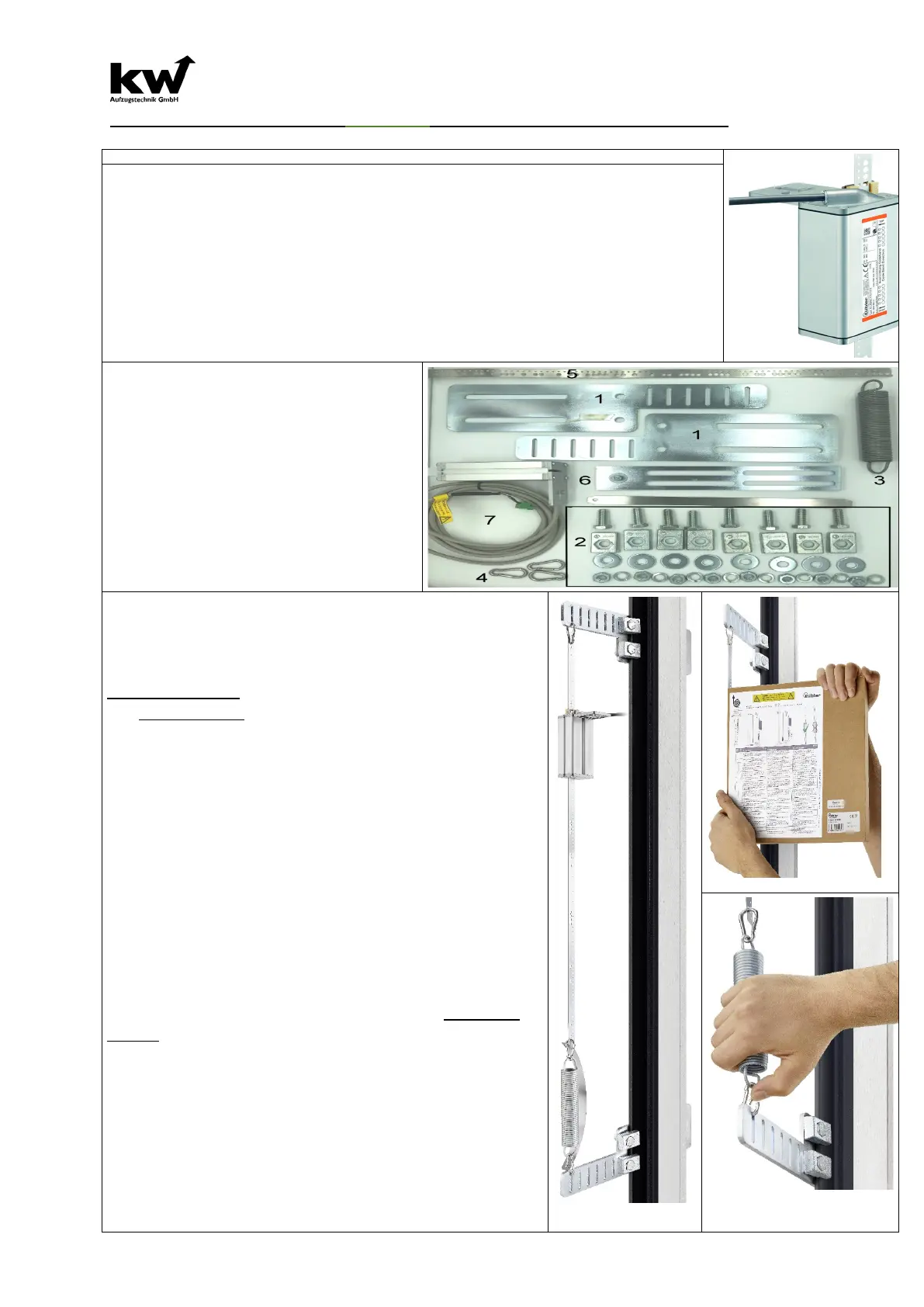
The Kübler LES02 is an absolute measuring system for determining the
position of the elevator car, consisting of the reading head, the steel band
and the mounting set.
The steel strip is fixed in the upper and
lower part of the shaft by means of
shaft flag holders. Pay attention to the correct spring preload.
The reader can be placed on the steel strip by means of a lateral opening.
The position of the large & small holes in the steel strip must be observed
when inserting!
Please also note the Kübler-LES02-SAFE installation instructions!
Mounting kit complete:
1 Shaft holder straight and angled
2 Screws & Clamps
3 Tension spring mounting at the
bottom
4 K-hook tape mounting on top
5 Steel tape
5 Holder for reader-unit with
attachment
7 Reader-unit with cable & plug
8 Stainless Steel Band
1. Mount the shaft flag holder in the shaft head in
compliance with legal and company-related safety
regulations. Depending on whether you are in-
stalling a central rail or backsack system, use the
shaft flag holder straight or angled and fasten it with
the fastening set 2.
2. Attach the upper end of the belt by inserting the
carabiner hook 4 into the shaft flag holder 1. Before
doing this, please check the orientation of the tape
using the large & small holes!
3. Drive down with the inspection and rewind the
tape directly. Please provide personal protective
equipment recommended for use.
4. Further assembly takes place in the shaft pit. Be-
fore entering the pit, ensure that the car is secured
against uncontrolled downward movement. For work
longer than 15 minutes, the car must be supported
in compliance with the safety regulations of the as-
sembly company!
5. Equivalent to steps 1 and 2, the lower shaft flag
holder 1 and the holder 2 for the magnetic tape are
to be mounted. A tension spring 3 is to be installed
and it must be saved with a Stainless steel band 8.
Decisive for the functionality is the spring preload. It
should be 170mm!