KW Aufzugstechnik GmbH OPERATING MANUAL DAVID-613
DAVID-D613-V125-E 13.04.2021 Page - 32 -
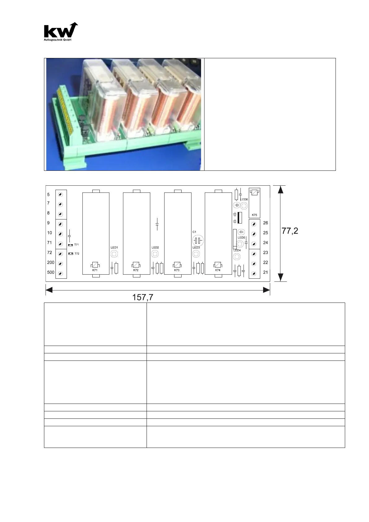
2.8 DESCRIPTION SECURITY CIRCUIT SIS-16-101
The Safety Circuit SIS16-101 has 4 safety re-
lays and a small relay for the level-indicator.
Screw terminals are on the right and on the
left of the Safety Circuit.
SIS16-101 is preparatory for the Mounting-
rail- assembly.
To the test of normal function of protection cir-
cuit is necessary to set the Jumper!
The security circuit has a type-examination
certificate for the EN.81-1/2-A3.
Relay- and Indicating elements:
K71= Zone Relays 71 with red LED-Display LED1
K72= Zone Relays 72 with red LED-Display LED2
K73=Controll Relay 73 with red LED-Display LED3
K74=Start Relay Drive/Releveling with red LED-Display LED4
K75=Concise Relay with red LED-Display LED 6
LED Status= Color green, Control display LED 5
(L x B x H) 157,7mm x 77,2mm x 65,0mm
Terminals 5,7 - 250V AC / 4A
Terminals 71,72 - +24V DC / 50mA
Terminals 200 - +24V DC / 100mA
Terminals 24 - +12V bis +24V DC / 250mA
power Akku
Terminals 26 - +12V bis +24V DC / 250mA Concise announcement
Ca. 1.000.000 Switching cycles
Reaction time from departure of
the zone to switch off maincon-
Worst-Case: 0,021 Seconds