5. Fi INJECTION SYSTEM MOVIE S 125i
5-13
ECU MOUDLE
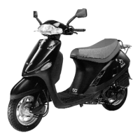
Removal
To dismantle the throttle cable
To disconnect the coupler from ECU module
To release the bolts of clamp of intake manifold
To remove the vacuum pipe
To remove the ECU module
Assembly
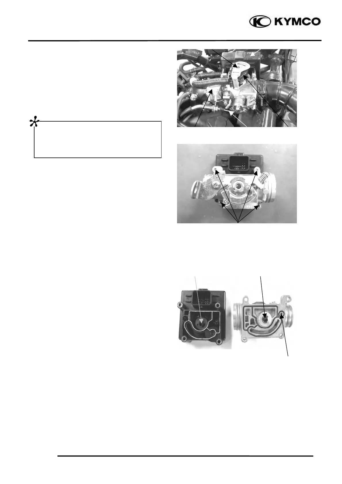
1.To confirm there is no any damage for O-ring,
which inside the throttle body set or replace it
with a new one.
2.To confirm there is no any damage on rib of
ECU set (yellow part in the illustration),
damage on rib or o-ring would cause air
leaking.
3.To aim the TPS’s knob of ECU set to axle of
throttle body then assemble the ECU module,
tightening four fixed screws evenly with
specific torque 0.3~0.37 kgf-m and install to
vehicle.
4.Connecting diagnostic tool to the diagnostic
connector, to check if throttle position and
output voltage from TPS are out of the range.
If the voltage measured is out of the range, refer
to page 5-16 as inspection or readjustment of the
output voltage of throttle.
Rod ECU MODULE
Clamp of manifold Throttle cable Stopper
Fixed screws
TPS Axle of throttle
RIB (YELLOW) O-ring
First, push the stopper of coupler to
release the rod, then pull back the rod to a
lower fixed position after hearing click
and then remove the coupler.