1.2 Parts and Functions
1-9
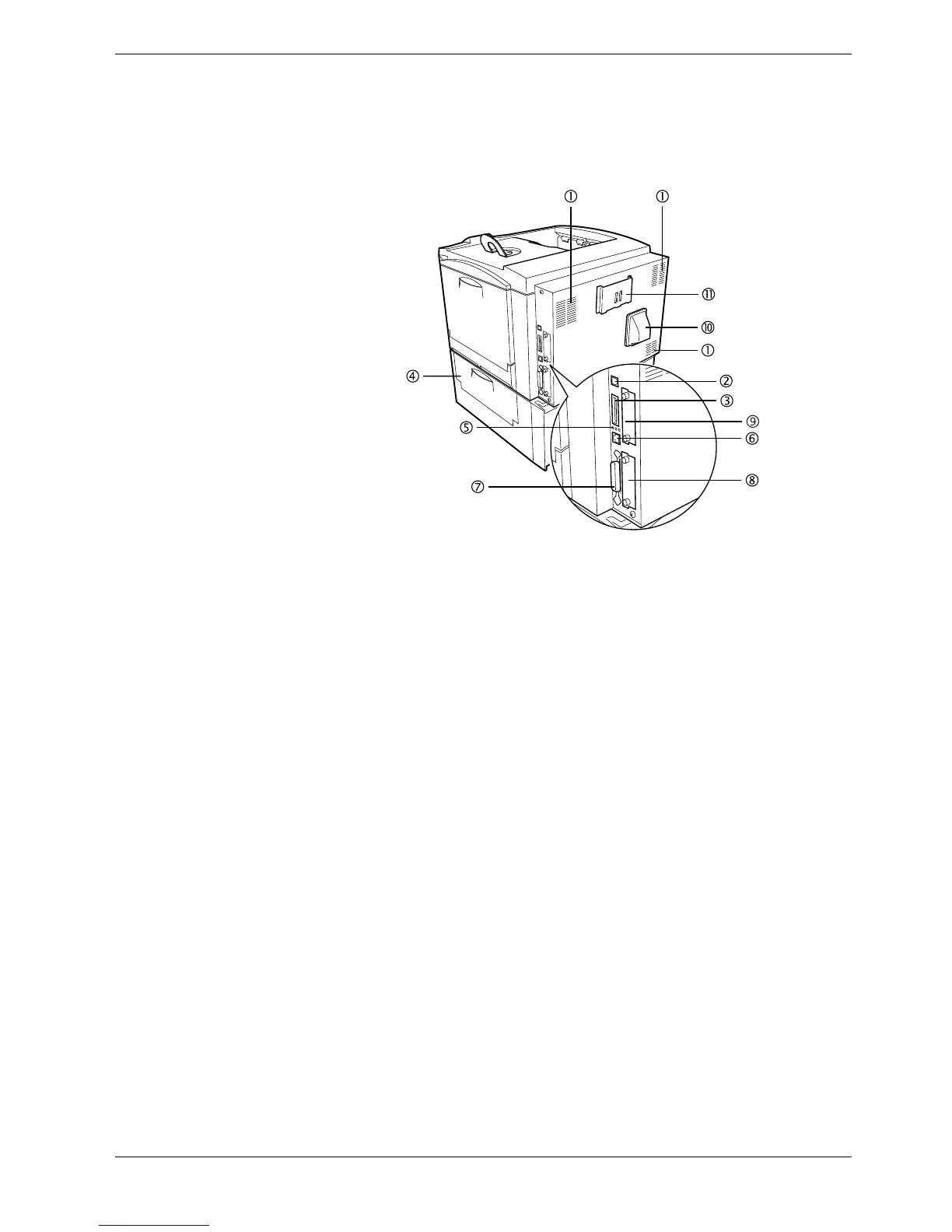
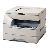
1.2.3 Rear
Figure 1-4
1Vents
Air is purged through these vents to cool down the inside.
2 USB Interface Connector
This connector is a USB interface that conforms to the Full-Speed USB 2.0. Use a USB
cable between this connector and the USB port on a computer.
3Memory Card Slot
This slot receives a memory card. A memory card can hold fonts, macros, forms, etc.,
that can be downloaded in the printer’s memory. For details, see Appendix A Options,
section A.3.1 Memory Card on page A-7.
4 Paper Feeder Right Cover
This cover is opened to clear paper jams in the paper feeder section.
5 Network indicators
These indicators light according to the communication status with the network.
10BASE-T indicator (10): Lights when you are connected to the network at 10 Mbps.
100BASE-TX indicator (100): Lights when you are connected to network at 100 Mbps.
Status indicator (ST): Flashes during data communication.
6 Network Interface Connector
Connects to the network via a 10BASE-T/100BASE-TX network cable.
7 Parallel Interface Connector
This connector is for a standard Centronics parallel interface cable from the computer.
Connect this connector to the computer’s parallel port.
8 Option Interface Card Slot (Network/Serial) [OPT]
This slot holds an optional network interface card for network printing or a serial
interface board kit. (An optional Hard disk can’t be used in this slot.) For details see
Appendix A Options.