2008. 11
302H756860
1
A
1
D
C
A
B
CDE
DUCT OPTION UNIT Installation
Instructions
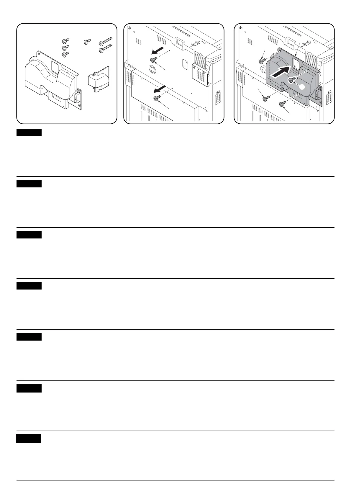
Supplied parts
A DUCT A...................................................... 1
B DUCT B...................................................... 1
C M3 x 8 tap-tight P screw ............................ 3
D M3 x 8 tap-tight S screw ............................ 1
English
E M3 x 20 tap-tight P screw
(100-volt models only) ............................... 2
1. Remove the two screws (1).
2. Attach DUCT A (A) using the following
screws:
Screws (1) removed in step 1: 2
M3 x 8 tap-tight P screw (C): 1
M3 x 8 tap-tight S screw (D): 1
IInstructions d'installation du Module
encrier fourni en option
Pièces fournies
A Encrier A .................................................... 1
B Encrier B .................................................... 1
C Vis P taraudées M3 x 8 ............................. 3
D Vis S taraudées M3 x 8 ............................. 1
Français
E Vis P taraudées M3 x 20
(modèles 100-volts uniquement) ............... 2
1. Déposer les deux vis (1).
2. Fixer l'encrier A (A) à l'aide des vis
suivantes:
Vis déposées à l'étape 1: 2
Vis P taraudées M3 x 8 (C): 1
Vis S taraudées M3 x 8 (D): 1
Instrucciones de instalación de la
unidad opcional Conducto
Partes suministradas
A Conducto A ................................................ 1
B Conducto B ................................................ 1
C Tornillo de ajuste P M3 x 8......................... 3
D Tornillo de ajuste S M3 x 8......................... 1
Español
E Tornillo de ajuste P M3 x 20
(sólo para los modelos de 100 voltios) ...... 2
1. Quite los dos tornillos (1).
2. Fije el conducto A (A) por medio de los
siguientes tornillos:
Tornillos (1) quitados en el paso 1: 2
Tornillo de ajuste P M3 x 8 (C): 1
Tornillo de ajuste S M3 x 8 (D): 1
Optionale Schachteinheit
Montageanleitung
Gelieferte Teile
A Schacht A................................................... 1
B Schacht B................................................... 1
C M3 x 8 P Passstift-Verbundschraube......... 3
D M3 x 8 S Passstift-Verbundschraube......... 1
Deutsch
E M3 x 20 P Passstift-Verbundschraube
(nur für 100-Volt-Modell)............................ 2
1. Entfernen Sie die beiden Schrauben (1).
2. Bringen Sie den Schacht A (A) mit den
folgenden Schrauben an:
Schrauben (1), die in Schritt 1 entfernt
wurden: 2
M3 x 8 P Passstift-Verbundschraube (C): 1
M3 x 8 S Passstift-Verbundschraube (D): 1
Istruzioni d’installazione dell’unità
condotto opzionale
Parti fornite
A Condotto A................................................. 1
B Condotto B................................................. 1
C Vite con testa a croce P M3 x 8 ................. 3
D Vite con testa a croce S M3 x 8 ................. 1
Italiano
E Vite con testa a croce P M3 x 20
(solo modelli a 100 volt)............................. 2
1. Togliere le due viti (1).
2. Fissare il condotto A (A) utilizzando le viti
seguenti:
Viti (1) rimosse al punto 1: 2
Vite con testa a croce P M3 x 8 (C): 1
Vite con testa a croce S M3 x 8 (D): 1
DUCT OPTION UNIT 設置手順書
同梱品
A DUCT A .............................. 1
B DUCT B .............................. 1
C ビス M3 × 8P タイト .................. 3
D ビス M3 × 8S タイト .................. 1
日本語
E ビス M3 × 20P タイト
(KMAS 取付時使用).................... 2
1. ビス (1)2 本を外す。
2. 下記のビスで、DUCT A (A) を取り付ける。
・手順 1 で取り外したビス (1): 2 本
・ビス M3 × 8P タイト (C): 1 本
・ビス M3 × 8S タイト (D): 1 本
导风管选购单元安装说明书
同装品
A 导风管 A ............................. 1
B 导风管 B ............................. 1
C M3 × 8 P 型自攻螺丝 .................. 3
D M3 × 8 S 型自攻螺丝 .................. 1
简体中文
E M3 × 20 P 型自攻螺丝
(仅限 100V 机型) .....................2
1. 取下 2 颗螺丝(1)。
2. 使用以下螺丝安装导风管 A(A):
在步骤 1 中取下的螺丝(1):2 颗
M3 × 8 P 型自攻螺丝(C):1 颗
M3 × 8 S 型自攻螺丝(D):1 颗
1
1
 Loading...