LACO PROTOCOL DESCRIPTIONS TITANTEST™
105
© 2018 LACO TECHNOLOGIES, INC. - TitanTest itra01en1-07 SB.fm - 1807
11.Interfaces and Protocols
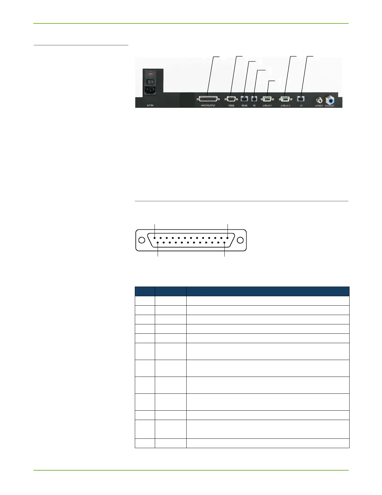
Fig. 41: Interface connections at the back of the device
a INPUT/OUTPUT: Control and output signals
b RS232**: Connection for computer
c RS485**: Connection for computer
d RC: Remote control or wireless transmitter
e RELAY 1: Relay output
f RELAY 2: Relay output
g LP: Connection for sniffer probe
11.1 INPUT/OUTPUT interface
Input and output signals, 25-pin, D-sub, sockets
Fig. 42: INPUT/OUTPUT: Control and output signals
Table 49: INPUT/OUTPUT: Control and output signals
Pin Assignment Explanation
1 Canal 1 Analog output 0 … 10 V, Ri 3 . (see table 13, page 35)
2 Channel 2 Analog output, data as above (see table 13, page 35)
3 AGND Reference potential of analog outputs, galv. insulated
4 Audio output (headphones or active speakers)
5 Reference potential to audio output
6 … 13 DI 1 … 8** Digital inputs, +18 … 30 V (approx. 5 mA). The functions are triggered by the posi-
tive flank. Same level as the control unit.**
6 Start/Stop** Starts the measurement in Ready-to-start state and stops the measurement in Mea-
suring state.**
7 Vent** Venting with setting "Venting manual" (see chapter 6.4.4: "Define evacuation time &
vent", page 45)**
8 ZERO** Function of the ZERO key.**
If pressed longer than 3s, ZERO is canceled.**
9 Calibrate** Starts the calibration or for confirmation of "Calibrate Acknowledge" (PIN 19)**
10 PARA 2** Upon activation: "Loading parameter set 2."**
Upon deactivation: "Loading parameter set 1."**
11 Not used
** Feature not available in T
ITANTEST™ Maintenance model