PLMNL0232 REV. H Effective Date: 01/14/19 63 FiberCUT
®
2D Operation Manual
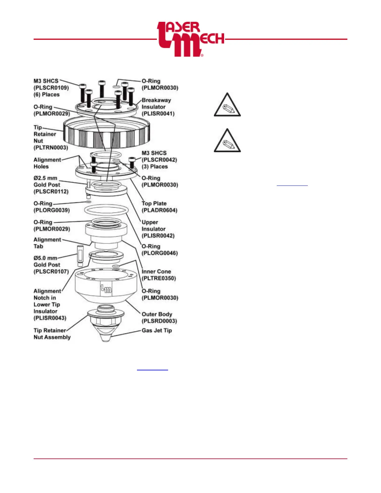
Figure 72
16. If desired, remove and/or replace the
gas jet tip according to Section 5.2.
To reassemble the tip assembly:
Worn or damaged o-rings were
replaced during the disassembly
procedure.
Replace any other worn or damaged
components during the reassembly
procedure.
For steps 17 to 28, see Figure 72.
17. If necessary, replace the gas jet tip
and/or tip retainer nut assembly
according to Section 5.2.
18. Thread the 2.5 mm (smaller) gold post
(PLSCR0112) into the inner cone.
Torque to 6 inch-pounds.
19. Push the lower tip insulator
(PLISR0043) onto the inner cone
(PLTRE0350) so that the inner cone
alignment tab seats in the lower tip
insulator alignment notch.
20. Orient the outer body so the alignment
flat (with the Laser Mechanisms logo)
faces you.
21. Insert the lower tip insulator and inner
cone with threaded stud into the outer
body so that the gold post is on your
left.
22. Thread the 5 mm (larger) gold post
(PLSCR0107) into the outer body.
Torque to 23 inch-pounds.