PPC600 Family Debugger | 7
©
1989-2022 Lauterbach
Warning
Signal Level
ESD Protection
All The debugger drives the output pins of the BDM/JTAG/COP connector with the
same level as detected on the VCCS pin. If the I/O pins of the processor are 3.3 V
compatible then the VCCS should be connected to 3.3 V.
See also System.up errors.
Supported debug voltage:
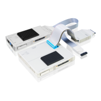
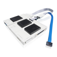
Debug cable with blue ribbon cable 2.5 … 5.0 V.
Debug cable with gray ribbon cable 1.8 … 5.0 V (Available since 03/2004).
WARNING: To prevent debugger and target from damage it is recommended to connect or
disconnect the Debug Cable only while the target power is OFF.
Recommendation for the software start:
1. Disconnect the Debug Cable from the target while the target power is
off.
2. Connect the host system, the TRACE32 hardware and the Debug
Cable.
3. Power ON the TRACE32 hardware.
4. Start the TRACE32 software to load the debugger firmware.
5. Connect the Debug Cable to the target.
6. Switch the target power ON.
7. Configure your debugger e.g. via a start-up script.
Power down:
1. Switch off the target power.
2. Disconnect the Debug Cable from the target.
3. Close the TRACE32 software.
4. Power OFF the TRACE32 hardware.