Assemble blade to blade carrier assembly.
Torque blade mounting screws to
385
in.-
13
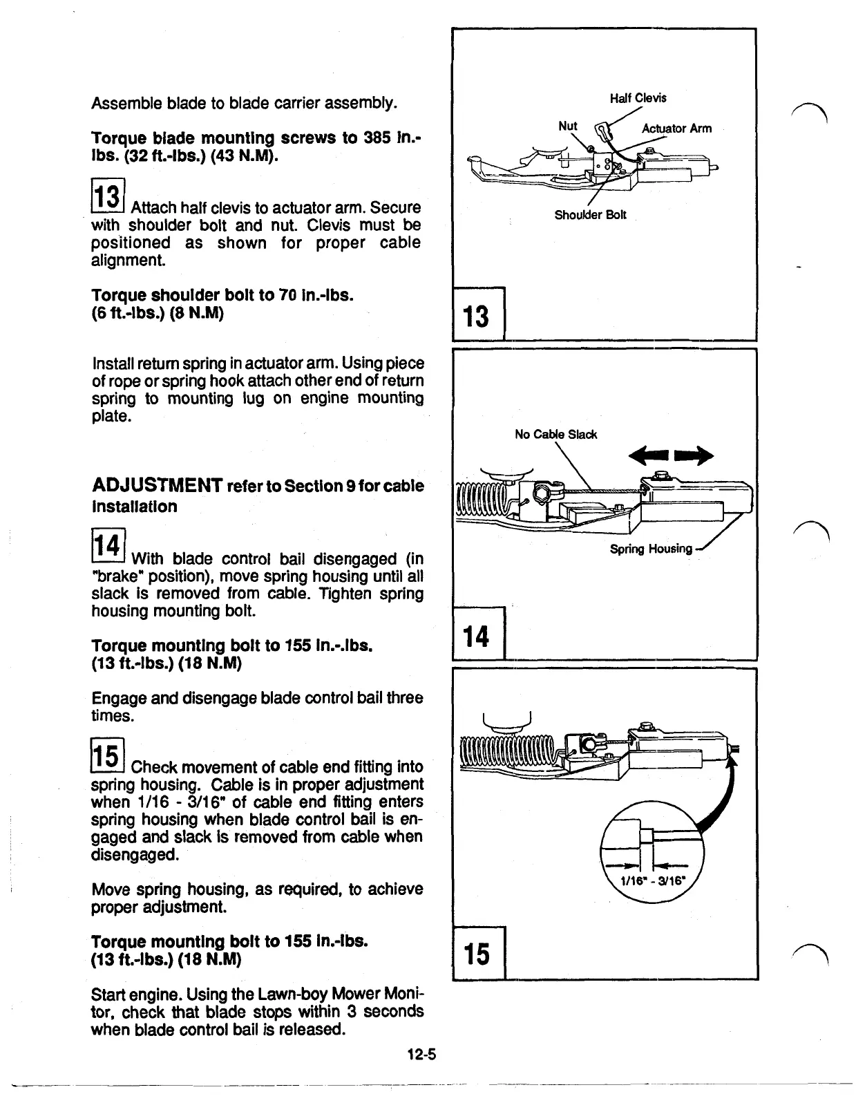
Attach half clevis to actuator arm. Secure
with shoulder bolt and nut. Clevis must be
positioned as shown for proper cable
alignment.
Torque shoulder bolt to
70
in.-lbs.
IbS.
(32
ft.-lbs.) (43
N.M).
(6
ft.-lbs.)
(8
N.M)
Install return spring in actuator arm. Using piece
of rope or spring hook attach other end of return
spring to mounting lug on engine mounting
plate.
ADJUSTMENT
refer to Section 9
for
cable
installation
14
With blade control bail disengaged (in
"brake" position), move spring housing until all
slack
is
removed from cable. Tighten spring
housing mounting bolt.
Torque mounting bolt to 155 in.-.lbs.
Engage and disengage blade control bail three
times.
15
Check movement of cable end fitting into
spring housing. Cable is in proper adjustment
when
1/16
-
3/16"
sf
cable end fitting enters
spring housing when blade control bail is en-
gaged and slack
is
removed
from
cable when
disengaged.
Move spring housing,
as
required,
to achieve
proper adjustment.
Torque mounting
bolt
to
155 In.-lbs.
Start
engine. Using the Lawn-boy Mower Moni-
tor, check
that
blade stops within
3
seconds
when blade control bail is released.
(13 ft.-lbs.)
(18
N.M)
(13 ft.-lbs.) (18
N.M)
12-5
Nut
\
Half
Clevis
Shoulder
Bolt
I
No
Cable
Slack
N
I
Spring
Housing
"I
l5
 Loading...