HANDLE SHAFT ASSEMBLY
REPLACEMENT
Left Hand Side Removal
Follow
Removal
procedures as described in
HANDLE REPLACEMENT
steps
67
to
71.
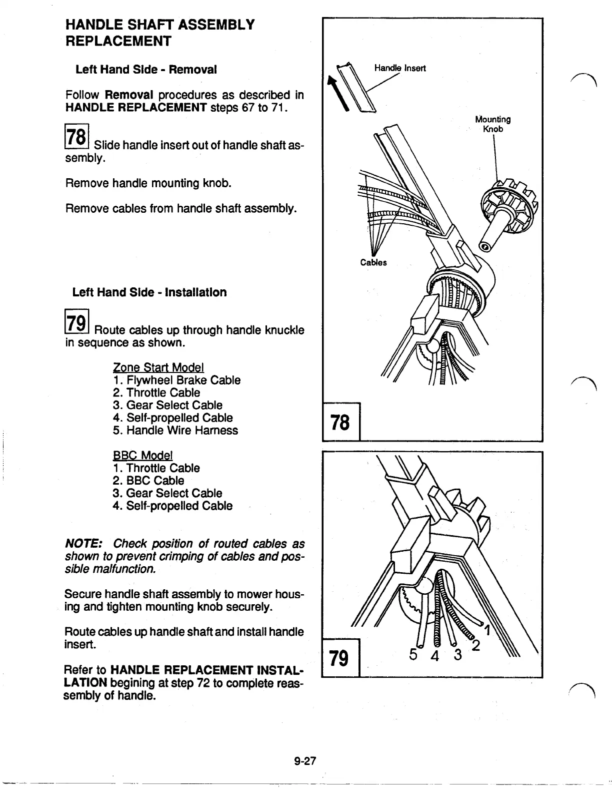
78
Slide handle insert out of handle shaft as-
sembly.
Remove handle mounting knob.
Remove cables from handle shaft assembly.
Left Hand Side Installation
79
Route cables up through handle knuckle
in sequence as shown.
Zone Start Model
1.
Flywheel Brake Cable
2. Throttle Cable
3.
Gear Select Cable
4.
Self-propelled Cable
5.
Handle Wire Harness
BBC Model
1.
Throttle Cable
2.BBC Cable
3.
Gear Select Cable
4.
Self-propelled Cable
NOTE:
Check position of routed
cables
as
shown
to
prevent crimping of cables and
pos-
sible malfunction.
Secure handle shaft assembly to mower hous-
ing and tighten mounting knob securely.
Route cables up handle shaft and install handle
insert.
Refer to
HANDLE REPLACEMENT INSTAL-
LATION
beginning at step 72
to
complete reas-
sembly
of
handle.
9-27
Mounting
78
I
 Loading...