7-18 LeeBoy Model 8616 Conveyor Paver
Maintenance
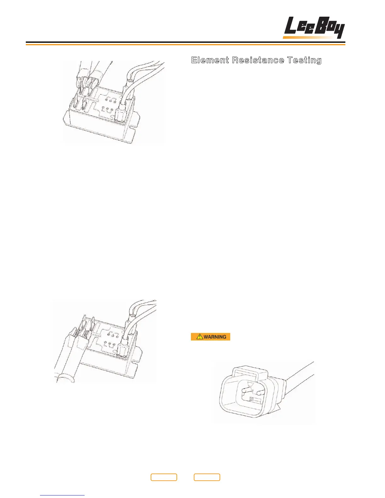
Element Resistance Testing
When a breaker in the control box has tripped, it must be
assumed that there may be a problem with wiring or an
actual element in the circuit.
Elements used to heat the screed are sized depending
on how much area and material they are required to
heat. The actual resistance of the element will vary
depending on what wattage the element is in the specic
application.
To know that the element is correct, you should read a
resistance between 25 and 35 ohms. If the element is
bad, the reading will be very different from this range.
The element that is bad will most likely read “open” or it
will read very little resistance (less than 1 ohm) and will
indicate a short through the element.
1. Disconnect element one at a time from the
connection point on the lower side of the control
box.
2. Use an ohm meter and test the resistance through
the element between the two pins in the plug at the
end of the element cable (Figure 7-18).
NOTE: You do not have to test the plug attached to the
lower side of the control box.
3. Test between the two pins shown here with an ohm
meter.
4. Test plug at end of element wires.
5. Before the element is plugged back in, check each
wire (pin) with an ohm meter test lead, and place
the other lead on a bare steel section of the screed
frame. If there is any continuity through the element
to the frame, the element is bad and must be left
disconnected or replaced.
Fire Hazard! Do not attempt to operate
an element with a known short. Replace faulty
elements and wiring before using.
Element Plug End
Figure 7-18
First Terminal Set Testing
Figure 7-16
NOTE: Without 12VDC applied to the coil of the relay,
the contact terminals should have no continuity
through them. The contacts should be “open”.
If the contacts are closed, and you do not have
12VDC applied to the coil of the relay, your
contacts are not correct, and the relay should be
replaced.
3. With the ohm meter still on the contact terminals,
apply 12VDC to the coil terminals of the relay
(Figure 7-17).
NOTE: The contact terminals should now close and
show a path through them for the power to be
applied to the electrical elements. If the relay
does not work as described above, it may be
faulty, and should be replaced.
Second Terminal Set Testing
Figure 7-17
Return to
Last Viewed
Return to
Thumb Index