7-10 LeeBoy Model 8616 Conveyor Paver
Maintenance
1
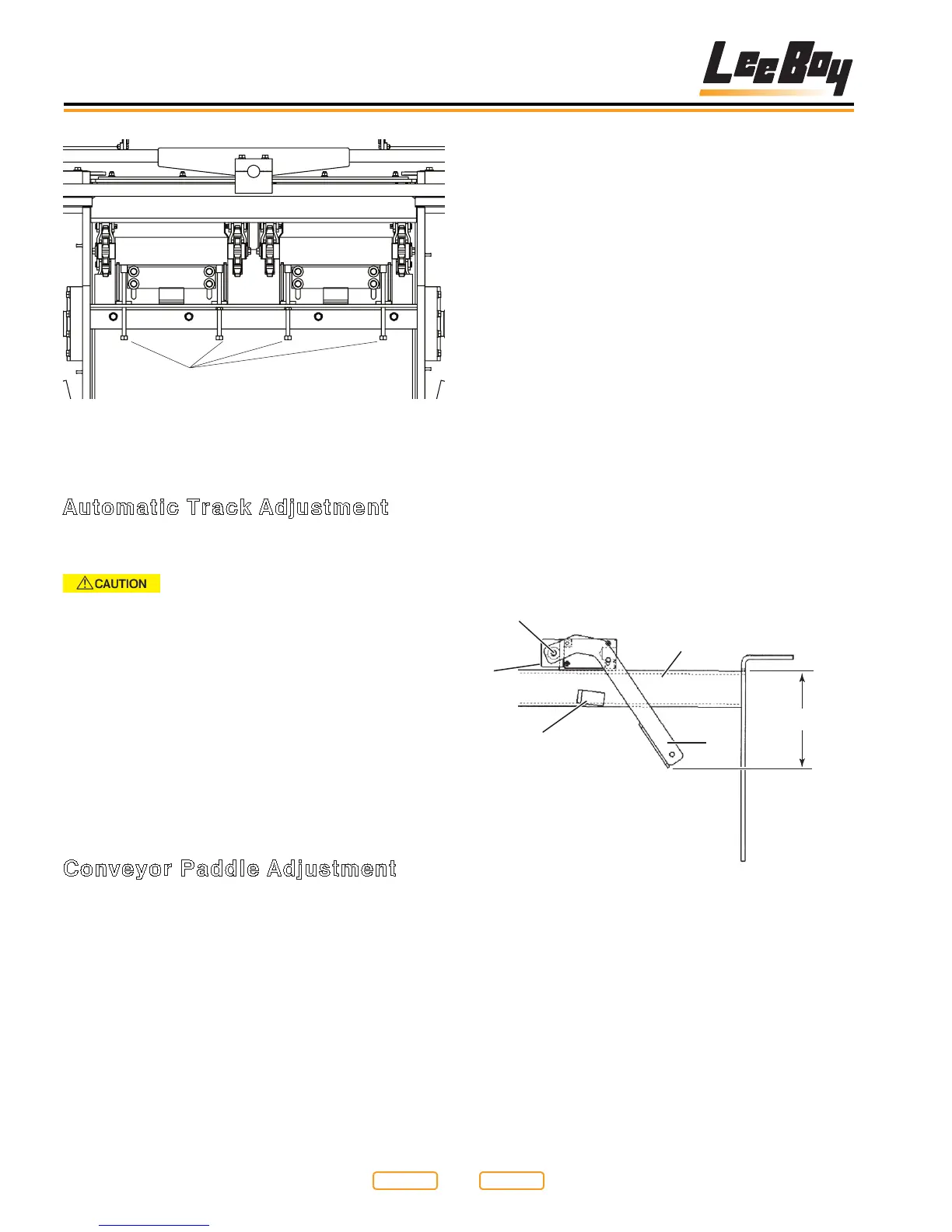
Conveyor Flight Chain From Below
Figure 7-5
1 - Adjustment Bolt
Automatic Track Adjustment
NOTE: Failure to maintain adequate throttle setting may
cause improper adjustment to track.
When backing this paver with load,
maintain at least a three-quarter throttle setting.
Failure to do so may cause improper track tension,
resulting in poor performance and damage.
Hydraulic adjustment cylinders are automatic and
provide even tension on track that prevents excessive
wear to paver undercarriage. This feature requires the
operator, when backing with load, to maintain at least
three-quarter throttle setting. Hydraulic pressure below
three-quarter throttle is not adequate to maintain track
adjustment.
• Track Tension Pressure: 1200 psi
• Track Tension Relieving: 2300 psi
Conveyor Paddle Adjustment
For left conveyor paddle adjustment:
1. Loosen conveyor paddle bolt (Figure 7-6,3).
(Paddle will rest against conveyor paddle stop.)
2. Turn limit switch shaft (Figure 7-6,4) counter-
clockwise (CCW) until conveyors cutoff.
3. Turn limit switch shaft (Figure 7-6,4) clockwise
(CW) until conveyors come back on, then turn about
1/16” (1.59 mm) more.
4. Tighten conveyor paddle bolt (Figure 7-6,3).
5. When adjusted correctly, paddle should be
approximately 5 1/2” - 5 1/4” (14 cm - 13.3 cm) from
top of tubing (that limit switch mounts to) (Figure
7-6,5) to lowest edge of conveyor paddle
(Figure 7-6,1).
NOTE: Repeat if necessary to get proper adjustment.
For right conveyor paddle adjustment:
1. Loosen conveyor paddle bolt (Figure 7-6,3).
(Paddle will rest against conveyor paddle stop.)
2. Turn limit switch shaft (Figure 7-6,4) clockwise
(CW) until conveyors cutoff.
3. Turn limit switch shaft (Figure 7-6,4) counter-
clockwise (CCW) until conveyors come back on,
then turn about 1/16” (1.59 mm) more.
4. Tighten conveyor paddle bolt (Figure 7-6,3).
5. When adjusted correctly, paddle should be
approximately 5 1/2” - 5 1/4” (14 cm - 13.3 cm) from
top of tubing (that limit switch mounts to) (Figure
7-6,5) to lowest edge of conveyor paddle
(Figure 7-6,1).
NOTE: Repeat if necessary to get proper adjustment.
1
5.50” - 5.25”
2
4
3
5
Conveyor Paddle Adjustment
Figure 7-6
1 - Conveyor Paddle
2 - Conveyor Paddle Stop
3 - Conveyor Paddle Bolt
4 - Limit Switch Shaft
5 - Tubing
Return to
Last Viewed
Return to
Thumb Index