KEY 4
Symbol Function
Decreases the throttle set point.
-
Decreases various settings.
STORED
CODES
Displays the stored codes when in the
diagnostic messages screen.
Moves cursor one slot at a time to the
right.
KEY 5
Symbol Function
Increases the throttle set point.
ACTIVE
FAULTS
Displays active faults.
Serves as the “Enter” key for menu
selections on certain screens.
+
Increases various settings.
Moves cursor one slot at a time to
the right and displays alternate menu
screens/choices.
Moves the cursor to the next cell when
customizing parameters on the home
screen.
ACK
Acknowledges active faults.
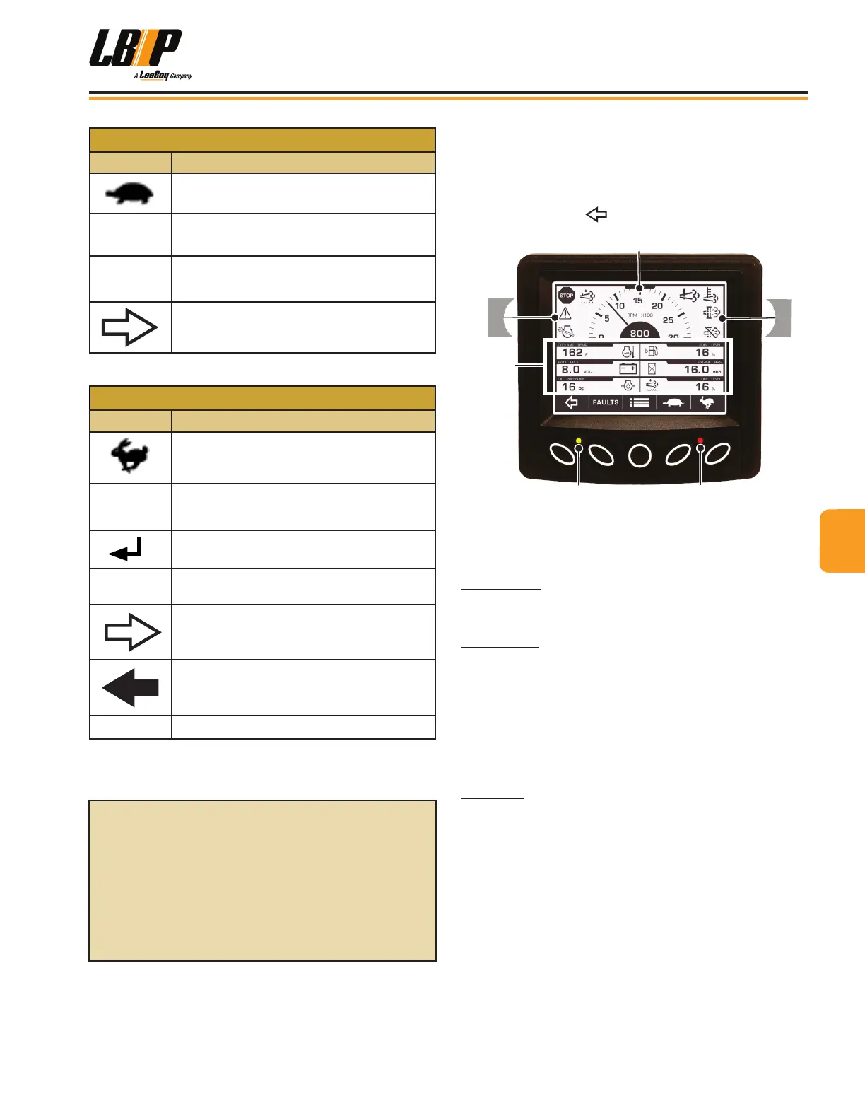
Gauge ScreenGauge Screen
Once the engine is running, the main gauge screen
appears. There are four gauge screens--two electronic
and two mechanical. You can scroll through the gauge
screens by pushing (Button 1). (Figure 4-12)
Tachometer
Parameters
Warnings
Warnings
Figure 4-12. Gauge Screen Parameters
The gauge screen also shows the tachometer, engine
information parameters and warning alerts.
Tachometer: The tachometer displays the engine
speed on a 3000-RPM dial. Engine hours are displayed
at the bottom of the tachometer area.
Parameters: The parameters sections of the screen
displays engine oil pressure, engine temperature,
engine hours, battery voltage, fuel level and other data.
(This machine is not equipped with a DEF tank, therefore
the DEF Level parameter does not function and always
displays 0%.)
NOTE: The target speed gauge appears for ve (5)
seconds when the user throttles the engine.
Warnings: Alerts and warnings appear in this area of
the screen to notify the operator a component needs
attention. The most important warning symbols are
shown in the upper left corner of the screen. Up to four
(4) symbols can be shown at a time.
It is important to heed these warnings and resolve the
issue promptly for optimum performance and preventing
damage to the engine or other components.
When a warning message is displayed, an amber light
will illuminate on the keypad. If the red light illuminates,
shut off the engine and resolve the problem to prevent
possible damage.
For detailed controller
instructions, please visit:
https://fwmurphy.com/uploaded/
documents/pdfs/00-02-0997.pdf
44
Operation
LB Performance CB95 Broom 4-11