Connection to Circuits
16 Power Analyzer NORMA 4000, NORMA 5000
EO1111G REV G
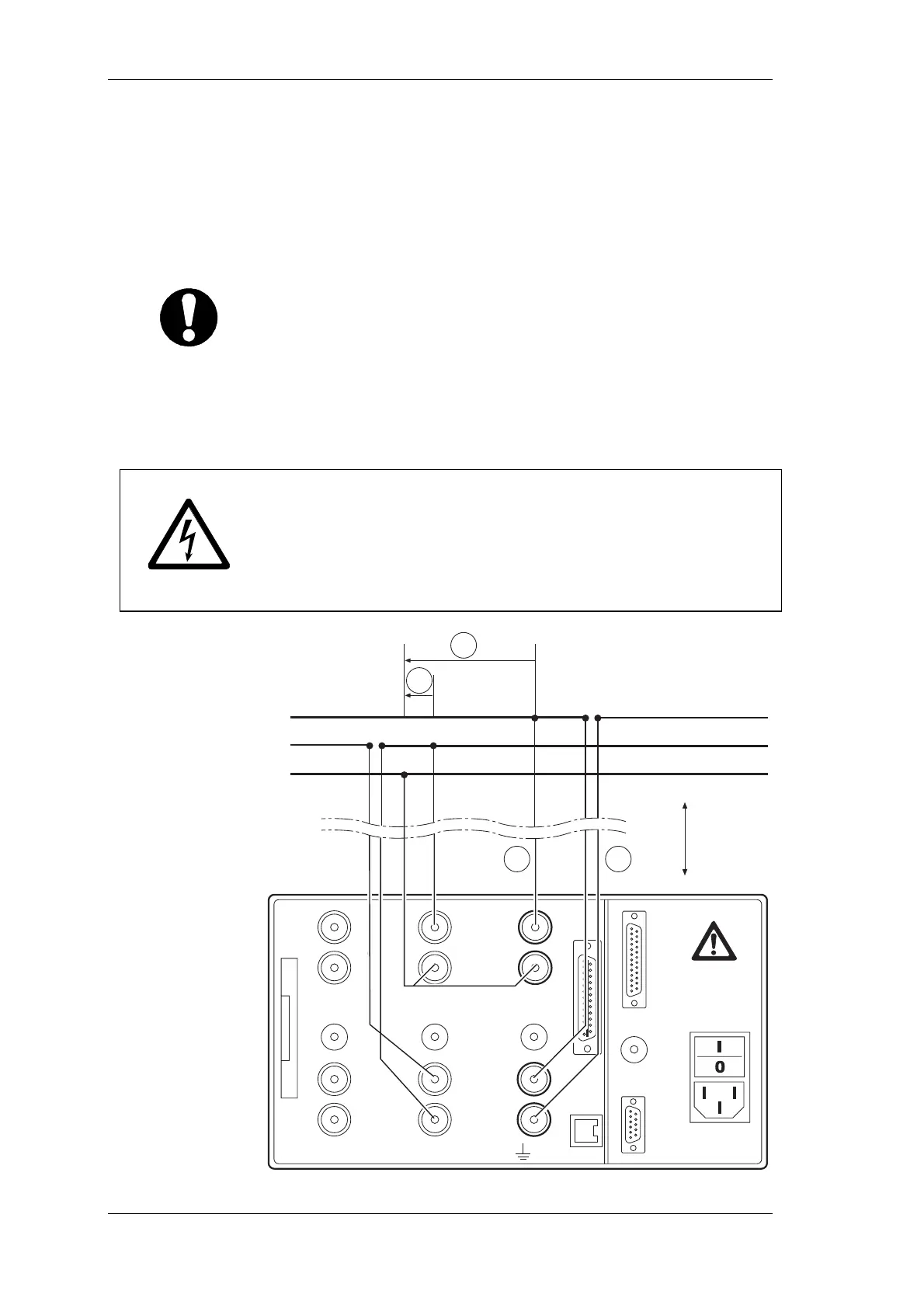
5.4 Aron circuit (triaxial/guard technique)
5.4.1 Direct connection
the Aron circuit is only available for 3-wire networks.
It is only required to measure two phases (currents I1 and I2 in the
connection diagram), as I1+I2+I3 must be 0.
Important
In most cases, the Aron circuit is not acceptable for measurements
on inverters, as there are capacitive leakage currents from the
windings to the housing!
Ensure that there is no overload at the current input of the
power analyzer.
If necessary, install appropriate fuses.
Fehler! AutoText-Eintrag nicht definiert.
Danger! Risk of electrocution!
Risk of injury when touching connections, internal circuits and
measuring devices that are not earthed.
Always adhere to the instructions regarding the sequence of
connection (see page 12).
1
HI
CURRENT
LO
10 A max
PROBE
EXT.SHUNT
10 V max
HI
VOLTAGE
LO
1000 V max
2
HI
CURRENT
LO
10 A max
PROBE
EXT.SHUNT
10 V max
HI
VOLTAGE
LO
1000 V max
3
ALL INPUTS MAX 1000V CATII TO
L2
max. 10 m
L1
L3
I
1
I
2
U
13
U
23