Design and functions
Power Analyzer NORMA 4000, NORMA 5000 7
EO1111G REV G
3 Design and functions
This chapter provides an overview of the terminals, ports and
interfaces of the power analyzer, as well as a list of display and
operating devices and a brief introduction to the basic functions of
the unit.
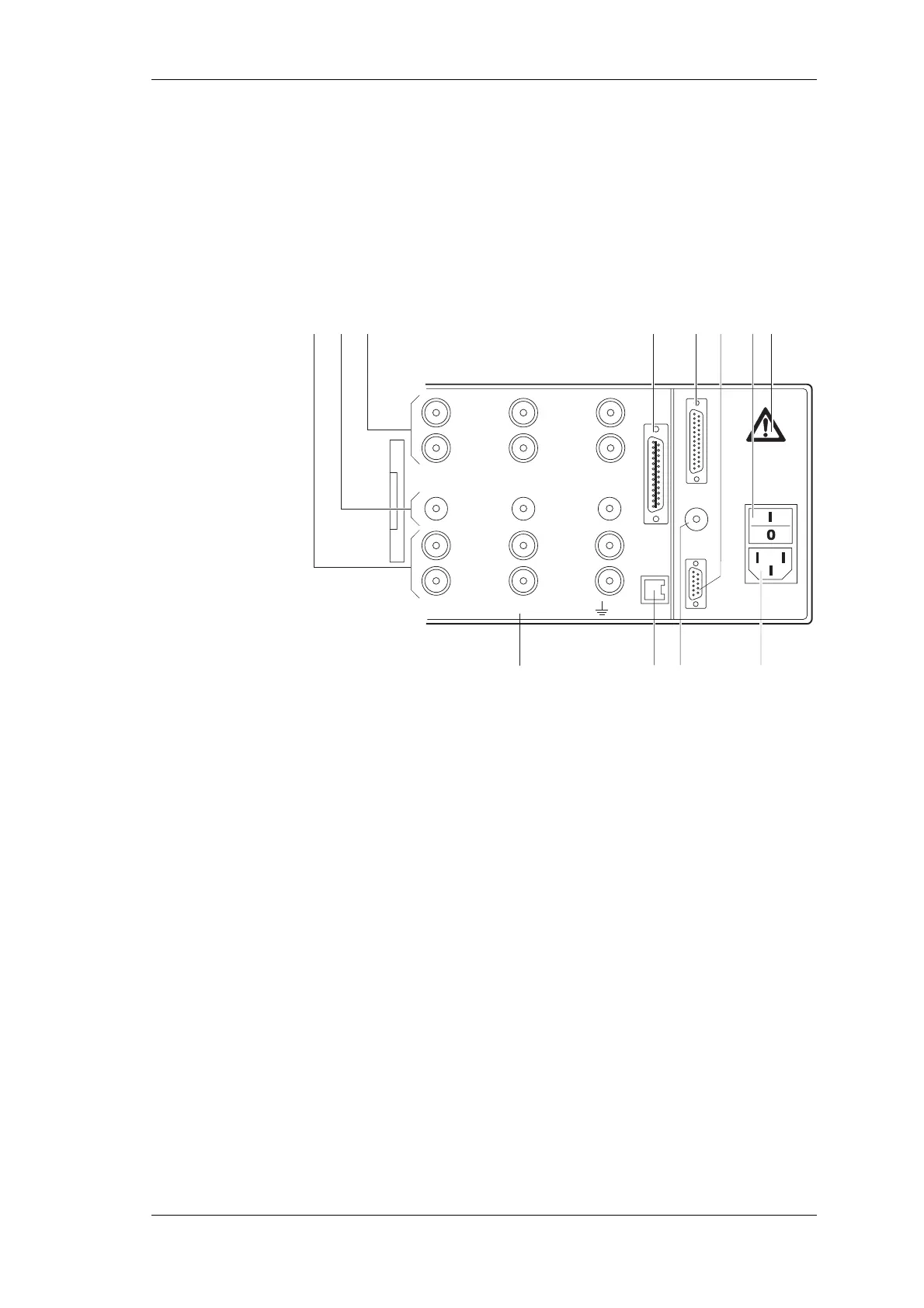
3.1 Terminals (rear of housing)
1
HI
CURRENT
LO
10 A max
PROBE
EXT.SHUNT
10 V max
HI
VOLTAGE
LO
1000 V max
2
HI
CURRENT
LO
10 A max
PROBE
EXT.SHUNT
10 V max
HI
VOLTAGE
LO
1000 V max
3
4 5 6 7
8910
123
ALL INPUTS MAX 1000V CATII TO
11
12
1 Measuring inputs for current (channels 1 ... 6)
HI: Conductor, positive
LO: Conductor, negative
2 Measuring inputs for shunts (channels 1 ... 6)
3 Measuring inputs for voltage (channels 1 ... 6)
HI: Conductor, positive
LO: Conductor, negative
4 IEEE488 interface (optional)
5 Port for PI1 interface
6 Serial interface (RS 232)
7 Power switch
I: ON
0: OFF
8 Mains connection
9 Input for external synchronisation signal
10 IF2 network adapter (LAN) (optional)
11 Warning regarding max. voltage to earth
12 Warning symbol; danger, observe operating instructions