Design and functions
8 Power Analyzer NORMA 4000, NORMA 5000
EO1111G REV G
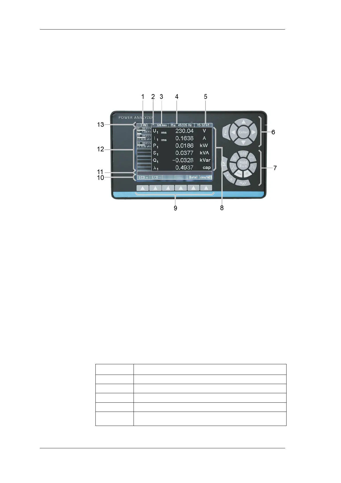
3.2 Operating controls and display
The display, operating controls and function keys are located at
the front of the device. The display consists of a menu bar, a
section in which the measured values and the channel settings are
shown and the assignment bar for the function keys.
1 Display of configuration;
menu item General Setup
2 Menu item Integration Setup / Motor-Generator Setup
3 Measurement status / display of average time
4 Display of synchronisation source frequency;
menu item Timing & Sync Setup
5 Display of time;
menu item Clock Setup
6 Navigation keys
7 Measuring keys
8 Display for measured values
9 Function keys
10 Assignment bar for function keys
11 Information row
12 Status display for channels 1 to 6 (including measuring
range, coupling and modulation bar);
menu items Current Channel Setup and Voltage
Channel Setup
13 Menu bar with menu items
Status Description
M
Memory record active
T
Wait for Trigger start condition(memory)
R
Measurement active (Run mode)
H
Measurement stopped (Hold mode)
∫
Integration of selected values active