Configuration
32 Power Analyzer NORMA 4000, NORMA 5000
EO1111G REV G
Important
If you select Set all to apply the configuration to all channels, only
the scale factor is transferred. If shunt values U/I are entered, the
scale factor is always 1, and Set all is not available. If probes are
used, it is generally easier to enter the transducer ratio, and Set all
is thus not recommended.
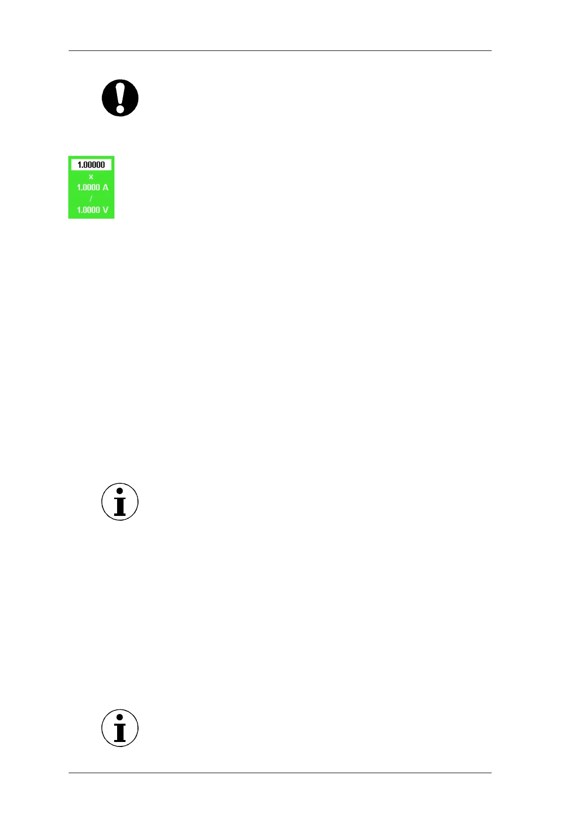
Move the cursor to the value in column Scale and press Enter.
A dialog window showing the scale formula is displayed.
Select a value for each parameter and confirm with Enter.
The settings are shown in column Scale.
Save the settings with SAVE in the desired configuration.
By configuring the coupling, you determine the current you wish to
analyse. Select AC to analyse alternating currents; select DC to
analyse direct and alternating current.
Move the cursor to the field in column Coup and press Enter.
The options AC and DC are displayed.
Select AC or DC and confirm with Enter.
The settings are shown in column Coup.
If you wish to configure all three current channels in this way,
press Set All.
Save the settings with SAVE in the desired configuration.
The anti-aliasing filter is located in the measuring channel. It is a
prerequisite for the correct analysis of FFT data. The default
configuration is ON. The anti-aliasing filter has a cut-off frequency
of 1/10 of the sampling frequency. At half the sampling frequency,
no signal reaches the A/D converter.
Note
For broadband numerical measurements in lighting technology, set
the filter to OFF.
If measurements at high frequency are made without filter, it is not
possible to correctly analyse the signals, due to aliasing. Please
refer to chapter 7.11 ”Undersampling / Aliasing” page 37
Move the cursor to the value in column Level and press Enter.
The options AC and DC are displayed.
Select the desired value and confirm with Enter.
The entered value is shown in column Level.
If you wish to configure all three current channels in this way,
press Set All.
Save the settings with SAVE in the desired configuration.
Call up Current Channel Setup.
Note
To configure the voltage channels, proceed as described for the
current channels.
Configure
coupling
Configure filter
Call up Voltage
Channel Setup