© Copyright Lenovo 2017 Chapter 8: VLANs 143
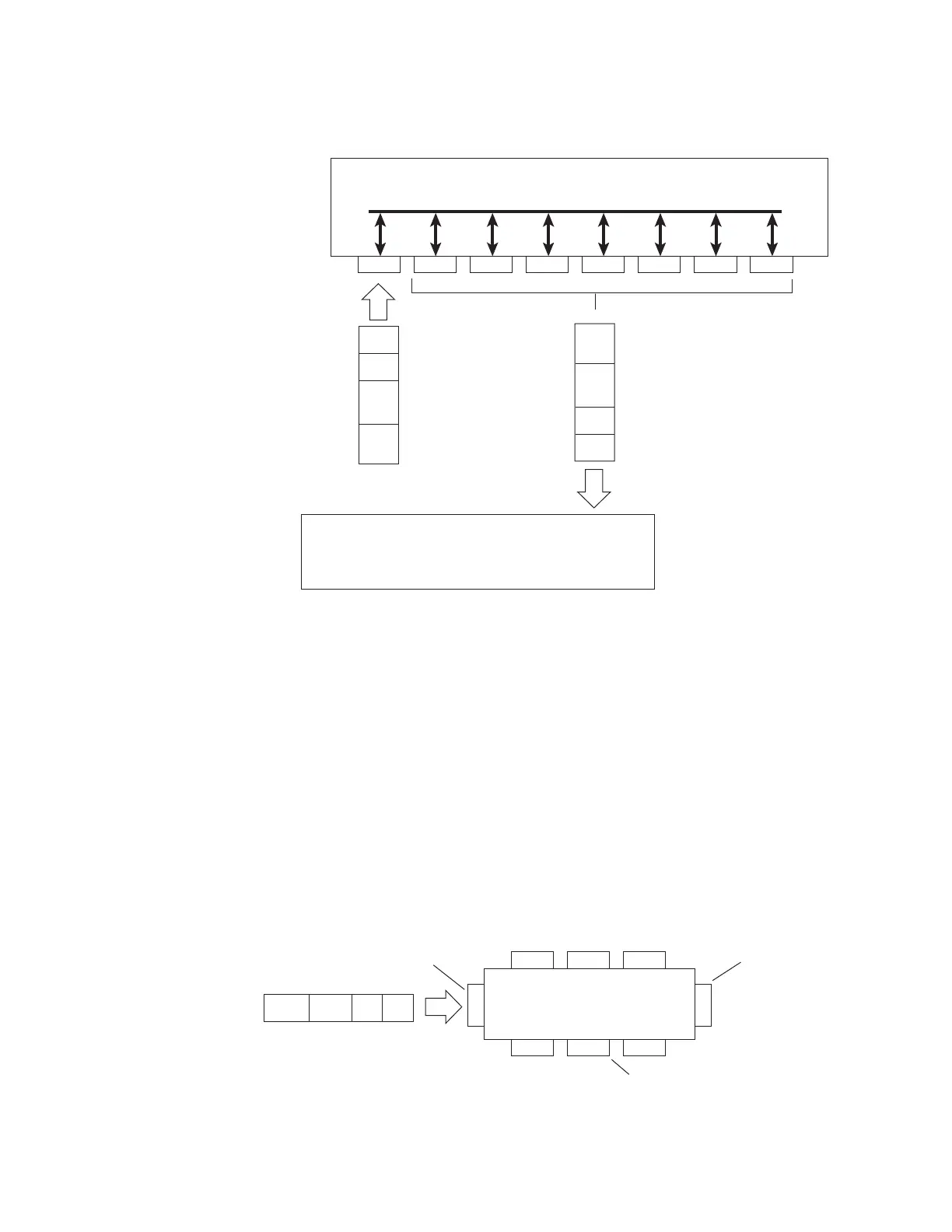
Figure 2. DefaultVLANsettings
Note: Theportnumbersspecifiedintheseillustrationsmaynotdirectly
correspondtothephysicalportconfigurationofyourswitchmodel.
WhenaVLANisconfigured,portsareaddedasmembersoftheVLAN,andthe
portsaredefinedaseithertaggedoruntagged(seeFigure 3throughFigure 6).
The
defaultconfigurationsettings forCN4093shaveallportssetasuntagged
membersofVLAN1withallportsconfiguredasPVID=1.Inthedefault
configurationexampleshowninFigure 2,allincomingpacketsareassignedto
VLAN1bythedefaultportVLANidentifier(PVID=1).
Figure 3throughFigure 6
illustrategenericexamplesofVLANtagging.In
Figure 3, untaggedincomingpacketsareassigneddirectlytoVLAN2(PVID = 2).
Port5isconfiguredasataggedmemberofVLAN2,andport7is configuredasan
untaggedmemberofVLAN2.
Note: Theportassignmentsinthefoll owingfiguresaregeneralexamples
andare
notmeanttomatchanyspecificCN4093.
Figure 3. Port‐basedVLANassignment
Port 1
DA
SA
Data
CRC
Incoming
untagged
packet
BS45010A
Port 2 Port 3 Port 4 Port 5
VLAN 1
802.1Q Switch
By default:
Key
All ports are assigned PVID = 1
All external ports are untagged members of VLAN 1
All internal server ports are untagged members of VLAN 1
PVID = 1
Port 6 ...
DA
SA
Data
CRC
Outgoing
untagged packet
(unchanged)
Port 7
Port 6
DASADataCRC
BS45011A
Port 7 Port 8
Port 1
Port 4
Port 5
Port 2 Port 3
802.1Q Switch
PVID = 2
Untagged packet
Untagged member
of VLAN 2
Tagged member
of VLAN 2
B
e
f
o
r
e
 Loading...