8×digital input / output
5
The modular system
5.9
l
5.9-2
EDSPM-TXXX-3.0-04/2004
DIO 8xDC24V 1A
.0
L+
.1
.2
.3
.4
.5
.6
.7
F
1
2
3
4
5
6
7
8
9
L
10
EPM – T230 1A
1
2
0
3
–
+
2
1
3
4
5
6
7
8
9
10
.
Z
Z
Z
Z
DC 24 V
(DC +18 … +35 V)
epm-t027 epm-t028
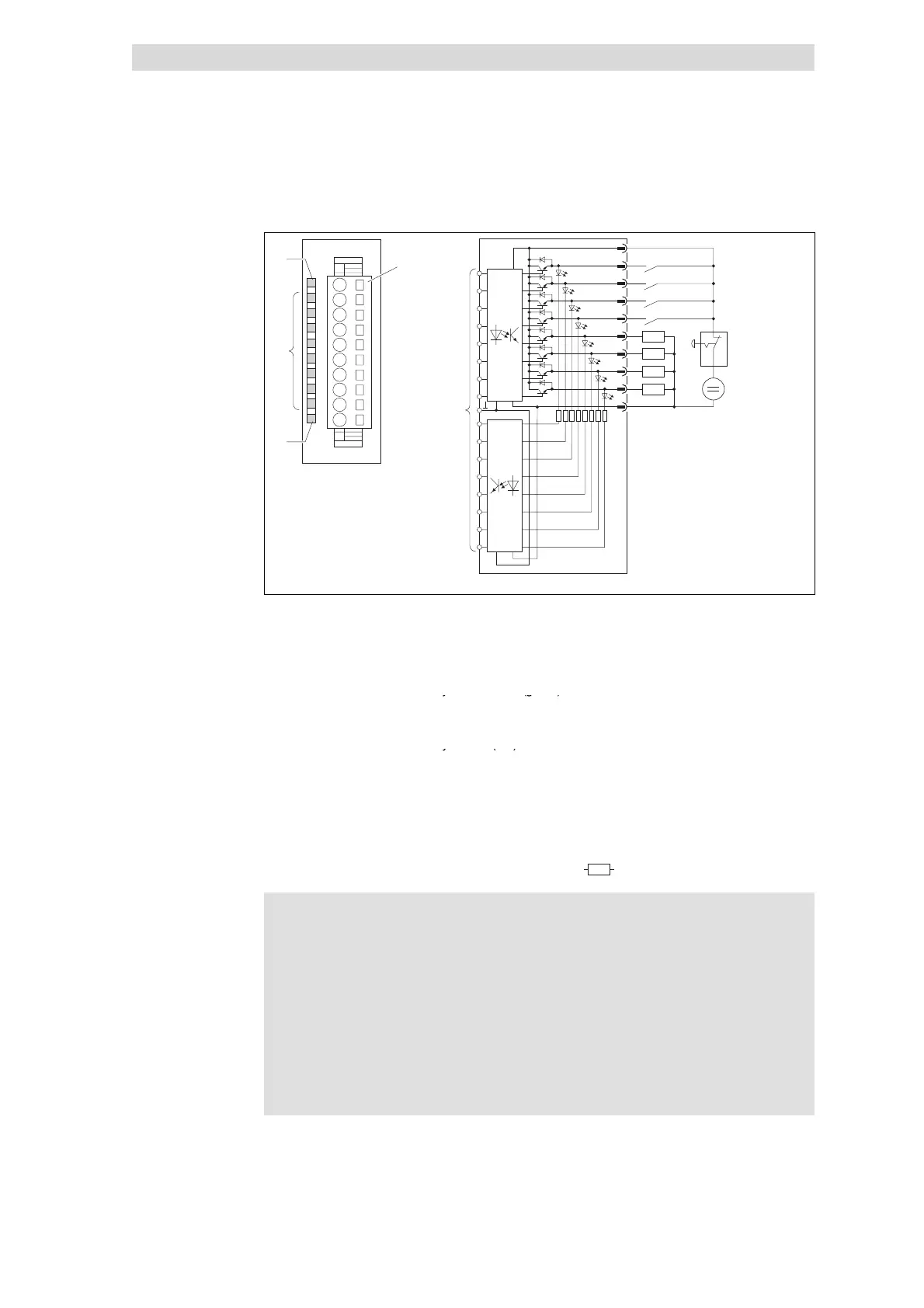
Fig. 5.9-2 Front view and connection of 8×digital input / output
Status display L+; LED (yellow) is lit
when a supply voltage is applied
Terminal strip assignment
details
1 DC 24 V supply voltage
2 Digital input / output E/A.0
Status display .0 ... .7; LED (green) is
3 Digital input / output E/A.1
lit when the corresponding output is
4 Digital input / output E/A.2
t
e
e
5 Digital input / output E/A.3
Status display F; LED (red) is lit in
6 Digital input / output E/A.4
case of overload, overheating or
7 Digital input / output E/A.5
s
o
tc
cu
t
8 Digital input / output E/A.6
9 Digital input / output E/A.7
10 GND (reference potential)
)
Connection to backplane bus
c Emergency-off switch
Z
Load
Stop!
If the voltage supply (DC 5 V via the backplane bus)fails, the
module will malfunction:
z
Switched outputs carry voltage if one input is assigned with a
HIGH level,
z
Themodulecanbedestroyedsincetheoutputsarenot
resistant to short circuits anymore.
The emergency-off switch ensures that when being operated, the
outputs do not carry any voltage and the inputs are not assigned
with a HIGH level.
Status display and terminal
assignment
 Loading...