EasyManua.ls Logo

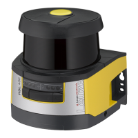
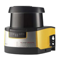
Leuze electronic RSL 420P User Manual

Leuze electronic RSL 420P
161 pages
To Next Page IconTo Next Page
Page #1 background imageLoading...
Page #1 background image
We reserve the right to make technical changes
EN • 2023-08-04 • 50137662
Original operating instructions
RSL 420P
Safety Laser Scanner with PROFIsafe Interface

Table of Contents

Questions and Answers:

Leuze electronic RSL 420P Specifications

General IconGeneral
TypeSafety laser scanner
Warning Field RangeUp to 50 m
Field of View/Scanning Angle270°
Protective Field SettingConfigurable
Operating Voltage24 V DC
Housing MaterialPlastic
Protection ClassIP65
Operating/Ambient Temperature0 °C to +50 °C
Resolution30, 40, 50, 70, 150 mm
Angular Resolution0.1°
OutputOSSDs
InterfaceEthernet
Safety StandardsIEC 61496-1
Protection Field RangeUp to 8.25 m

Summary

About this document

Applicable Documents

Lists related documents for comprehensive understanding.

Download Configuration Software

Instructions for obtaining the necessary software.

Symbols and Signal Words

Explains warning symbols and signal words used in the manual.

Safety

Intended Use and Environmental Factors

Covers intended use and environmental conditions affecting sensor operation.

Foreseeable Misuse

Details incorrect uses that could lead to hazardous situations.

Competent Persons

Outlines qualifications required for installation and operation personnel.

Laser Safety Notices

Provides safety information related to laser radiation and classification.

Device Description

Device Overview and Components

Introduces the sensor and its main components like scanner unit and connection units.

Interfaces and Connectivity

Details USB, Ethernet, and other connection interfaces for communication.

Display Elements and Indicators

Explains the function of LEDs and the alphanumeric display for status.

Mounting Options

Covers optional mounting systems and accessories for installation.

Configuration Software Sensor Studio

System Requirements and Installation

Details PC requirements and steps to install the Sensor Studio software.

Software User Interface

Overview of the graphical interface and its main areas for operation.

Configuration Project Management

Covers creating, loading, and managing configuration projects for the sensor.

Selecting Access Level

Explains user access levels and their permissions within the software.

Sensor Functions

Authorization Concept

Defines user access levels and their corresponding functional permissions.

Function Modes

Explains different operating modes and protective function configurations.

Resolution and Speed Settings

Details how to configure detection resolution and speed-dependent functions.

Field Pair Changeover

Describes how to configure and manage switching between different protective fields.

Applications

Stationary Guarding

Covers stationary danger zone and point of operation guarding applications.

Mobile Guarding

Details applications for mobile danger zone guarding on AGVs.

Side-tracking Skate Safeguarding

Explains safeguarding on transverse side-tracking skates.

Mounting and Installation

General Mounting Principles

Covers basic mounting, safety distances, locations, and field dimensioning.

Stationary Guarding Calculations

Safety distance calculations for stationary danger zone guarding.

Mobile Guarding Calculations

Minimum distance calculations for mobile applications on AGVs.

Mounting Accessories

Details available accessories like mounting systems and loop guards.

Electrical Connection

Electrical Supply and Interfaces

Covers voltage supply, functional earth, and available interfaces.

Connection Units Overview

Details different connection unit types like CU400P-3M12 and CU400P-4M12.

Connection Units CU400P-AIDA

Details connection units with AIDA connectors for copper and fiber optics.

Cable Lengths

Provides information on cable length limitations based on voltage drop.

Configuring the Safety Sensor

Defining Safety Configuration

Outlines the process for setting up the sensor's safety parameters.

PC Connection Methods

Describes how to connect the sensor to a PC via Ethernet, Bluetooth, or USB.

Configuring Protective Functions

Details how to set up protective functions, field pairs, and banks.

Transferring Configuration to Sensor

Explains the steps to download the configured project to the safety sensor.

Starting Up the Device

Initial Power On and Alignment

Steps for powering up and aligning the safety sensor correctly.

Unlocking Start/Restart Interlock

Procedures for safely enabling the start/restart interlock function.

Replacement Scanner Unit Startup

Guidance on starting up a replacement scanner unit.

PROFIsafe and PROFINET Integration

Overview

Introduces PROFIsafe and PROFINET communication for the safety sensor.

GSDML File

Explains the role and structure of the GSDML file for device description.

Integrating into PROFIsafe Network

Steps for network topology, addressing, and control configuration.

Configuring for Siemens TIA Portal

Detailed guide for setting up the sensor within Siemens TIA Portal.

Testing and Verification

Pre-Commissioning and Modification Checks

Procedures for initial startup and post-modification verification by integrators.

Periodic Testing by Competent Persons

Requirements for regular inspection and testing by qualified personnel.

Periodic Operator Checks

Routine functional checks to be performed by the machine operator.

Diagnosis and Troubleshooting

Failure Handling

Guidance on identifying and resolving faults using error messages and displays.

Diagnostics Display Codes

Explains the structure and meaning of diagnostic codes for fault identification.

Care, Maintenance, and Disposal

Replacing the Scanner Unit

Step-by-step instructions for replacing a defective scanner unit.

Cleaning the Optics Cover

Procedures for cleaning the sensor's optics cover to ensure performance.

Product Disposal

Guidelines for environmentally responsible disposal of the device.

Service and Support

Service Hotline and Repair Information

Provides contact details for support and information for repair services.

Technical Data

General and Safety-Relevant Specifications

Lists key safety standards, performance levels, and general specifications.

Dimensions and Drawings

Provides mechanical dimensions and drawings of the sensor and accessories.

PROFIsafe Status Profile

Details the logical and electrical signals within PROFIsafe modules.

Standards and Legal Regulations

Applicable National and International Regulations

Lists relevant directives and standards for safety sensors.

Order Guide and Accessories

Product Part Numbers

Lists part numbers for different sensor models and connection units.

Spare Parts and Accessories

Details available spare parts and optional accessories for the system.

EC Declaration of Conformity

Compliance with European Standards and Directives

States the product's development and manufacturing compliance with EU regulations.

Related product manuals