Standalone MX DVI-Plus family
User’s Manual
Section 2. Controls and connections Page 11 / 89
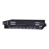
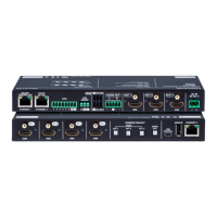
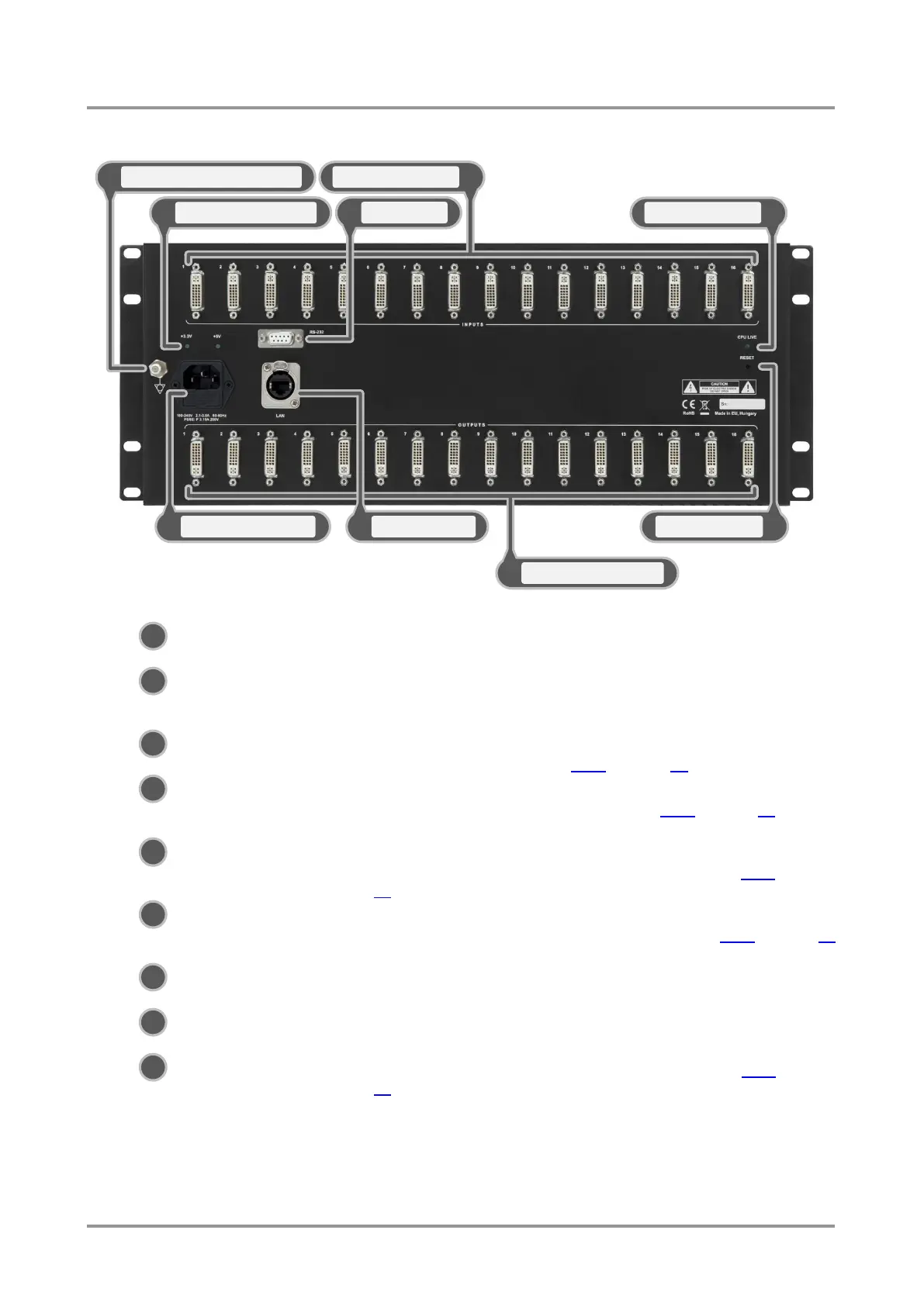
2.2. Rear view
Figure 2-2. Rear view
DC voltage indicators LED indicators for internal DC power voltages.
Power connector Standard IEC-320 C14 power connector. The router works with 100
to 240 Volts, 50 or 60 Hz power sources. The fuse can be replaced
with F3.15A type only!
Serial port 9 pole D-SUB female connector. Can be ordered with RS-232 or
RS-422 control. See section 2.3.4 on page 13 for more information.
Ethernet port Locking RJ45 connector. Remote control port for connecting the unit
to Local Area Network (LAN). See section 2.3.5 on page 13 for more
information.
Input connectors 29 pole DVI–I digital-only female receptacle connectors. Connect
DVI source devices to these connectors. See section 2.3.1 on page
12 for more information.
Output connectors 29 pole DVI–I digital-only female receptacle connectors. Connect
DVI sink devices to these connectors. See section 2.3.2 on page 12
for more information.
CPU live LED Continuously blinking LED if the CPU works properly.
Reset button Resets all internal hardware elements.
Equipotential connector Plug connector for potential equalization. See section 2.3.3 on page
12 for more information.
Info: MX12x12DVI-Plus rear panel differs only in that it has 12 input and 12 output connectors.
Info: MX9x9DVI-Plus rear panel differs only in that it has 9 input and 9 output connectors.