Standalone MX DVI-Plus family
User’s Manual
Section 2. Controls and connections Page 13 / 89
2.3.4. RS-232 / RS-422 control port
Lightware standalone DVI-Plus matrices can be remote controlled through industry
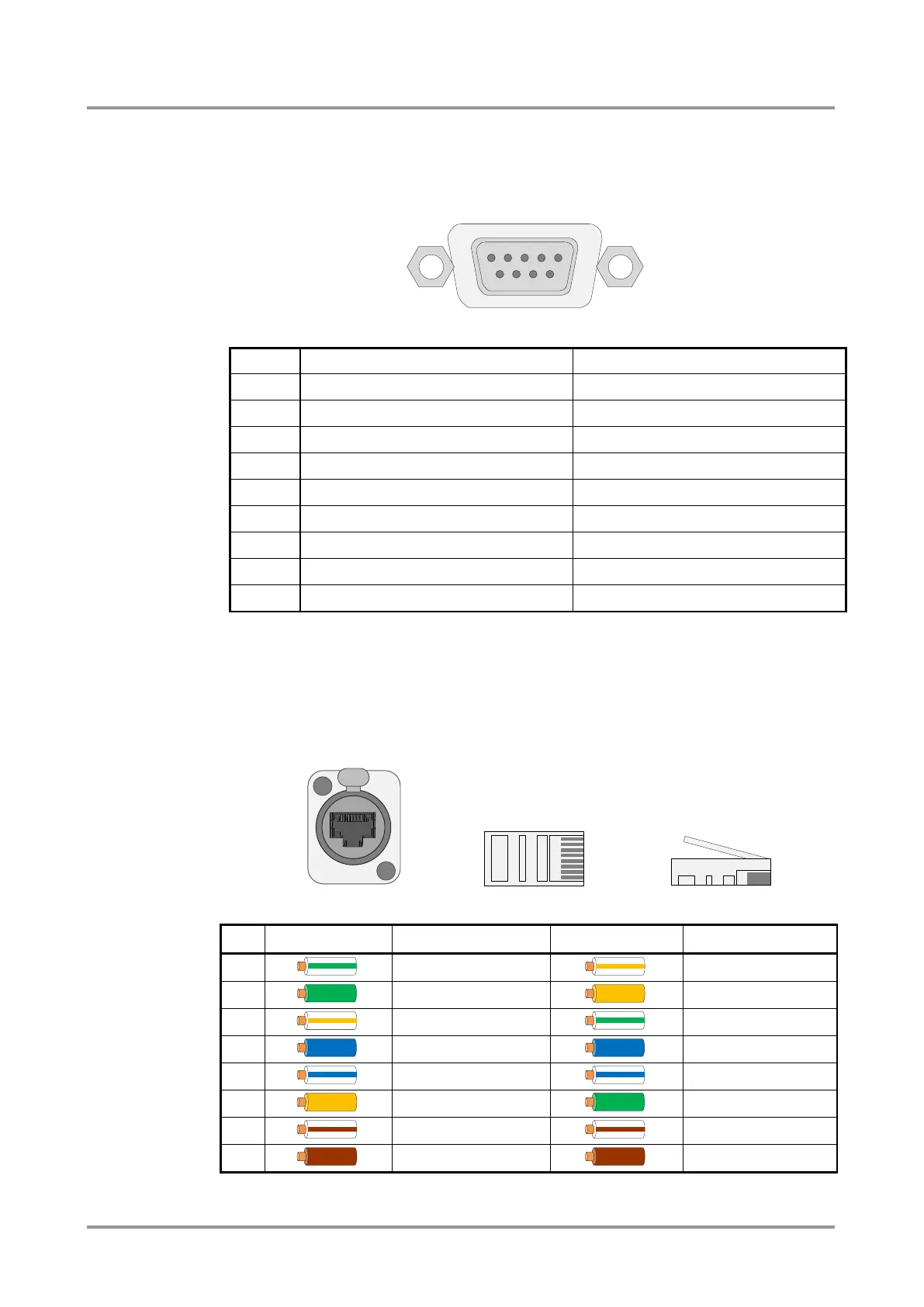
standard 9 pole D-SUB female connector located on the rear panel of the unit. The router
can be ordered with RS-232 or RS-422 control port.
Figure 2-3. D-SUB 9 pole female connector (DE9F)
TX- data transmit complement
TX data transmit (output)
DTR (internally connected to Pin 6)
RX- data receive complement
GND signal ground (shield)
GND signal ground (shield)
DSR (internally connected to Pin 4)
RTS (internally connected to Pin 8)
CTS (internally connected to Pin 7)
Table 2-2. D-SUB 9 pole pin assignments
2.3.5. Ethernet port
The matrix can be remote controlled via Ethernet as well. The matrix can be connected to
a LAN hub, switch or router with a UTP patch cable. If connecting to a computer directly, a
cross UTP cable has to be used! The robust Neutrik EtherCON connector ensures reliable
connection, however normal RJ45 connectors can be used as well.
The recommended termination is based on TIA/EIA T 568 A or TIA/EIA T 568 B standards.
Table 2-3. Recommended termination of TP cables