Page 32 / 89 Section 5. Software control – Using Lightware Device Controller (LDC)
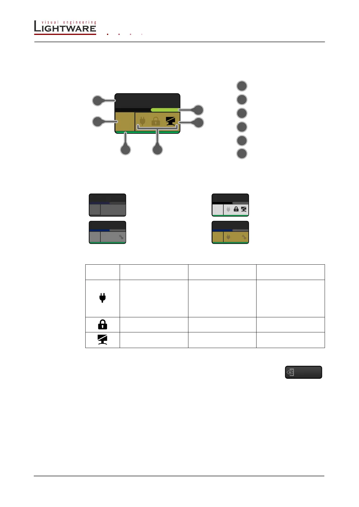
5.6.1. Port tiles
The colors of the port tiles and the displayed icons represent different states and
information about selected port:
Board type
(green means MX-DVID)
Signal present (green),
not present (grey)
Background colors (port state)
The colors of the port tiles represent different states of the port as follows:
Dark grey
Port is not available
(no board is installed)
Light grey
Port is available
State indicators
No information is
available about
connection status
Port is available but
inactive
Port is available and
sink / source is
connected (hotplug /
power +5V detected)
5.6.1. View mode
This mode was designed to display crosspoint state of a selected- and its
connected port(s).
Info: Crosspoint settings cannot be changed in View mode but port settings are available.
5.6.2. Crosspoint operations
Crosspoint changes can be made in Input switch mode and Output switch mode. The
working method is the same in both cases but the priority is different.
Input switch mode
The mode can be also named as ‘Input priority-mode’. In the mode an input port has to be
selected at first then the connected output port(s) is/are shown. Thus, the output port(s)
connected to the input port can be changed.