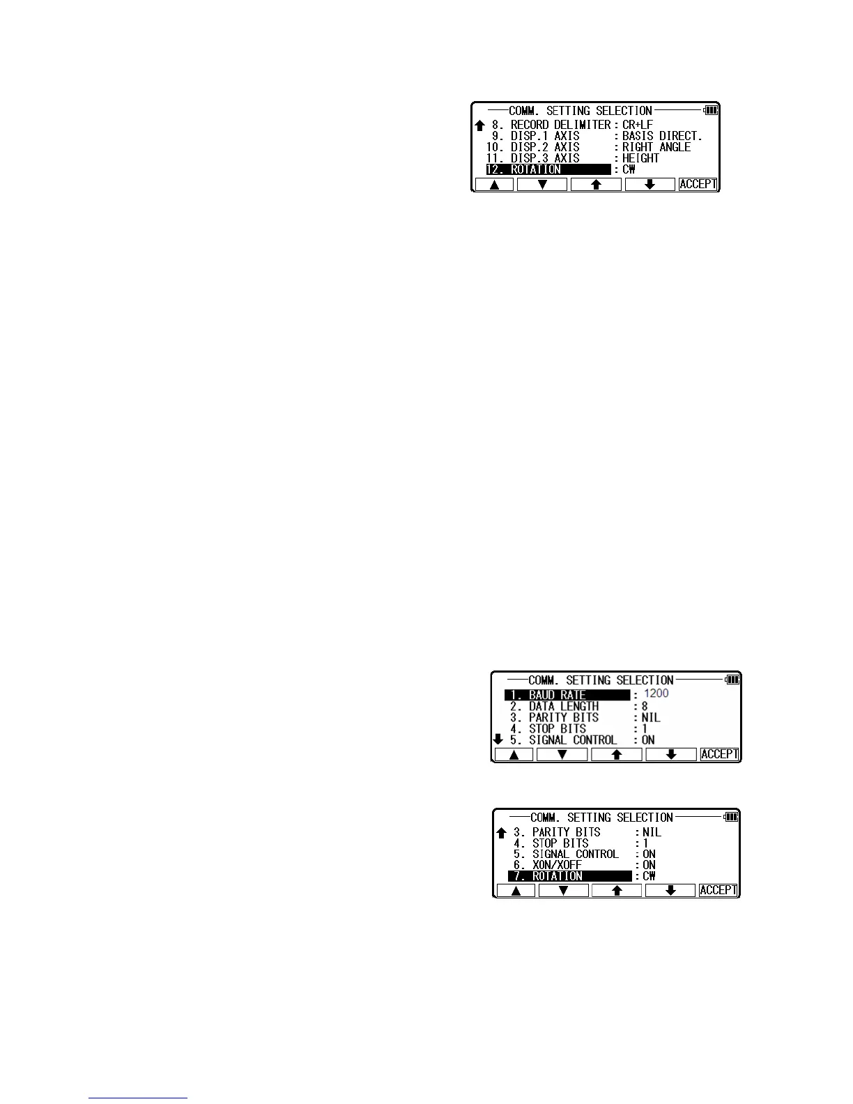
Press [ACCEPT] when all selections are made.
• DISP.# AXIS: BASIS DIRECT, RIGHT ANGLE, or HEIGHT is selected when
data is transferred between the TS and PC. (cfr. “11.2 Coordinate axis definition”)
They are used for matching coordinate system between definition in the instrument and
definition in the external device when they are different. However, it is necessary to match
the definition of the “Coord. Axis” between settings in “Communication setup” and
settings in “Coordinate axis definition” when same coordinate systems are used.
• Factory default setting of SENDING
1. BAUD RATE: 1200
2. DATA LENGTH: 8
3. PARITY BITS: NIL
4. STOP BITS: 1
5. SIGNAL CONTROL: ON
6. XON/XOFF: ON
7. PROTOCOL: ON
8. RECORD DELIMETER: CR+LF
9. DISP.1 AXIS: BASIS DIRECT
10. DISP.2 AXIS: RIGHT ANGLE
11. DISP.3 AXIS: HEIGHT
12. ROTATION: CW
[3. SEND POLAR DATA]
Select the 3. SEND POLAR DATA and press [ENT] to
view the following screen.
Press [ENT] to open the selection window.
Select each setting and press the [ENT].
Press [ACCEPT] when all selections are made.
• Factory default setting of 3. SEND POLAR DATA
1. BAUD RATE: 9600
2. DATA LENGTH: 8
3. PARITY BITS: NIL
4. STOP BITS: 1
5. SIGNAL CONTROL: ON
34
 Loading...