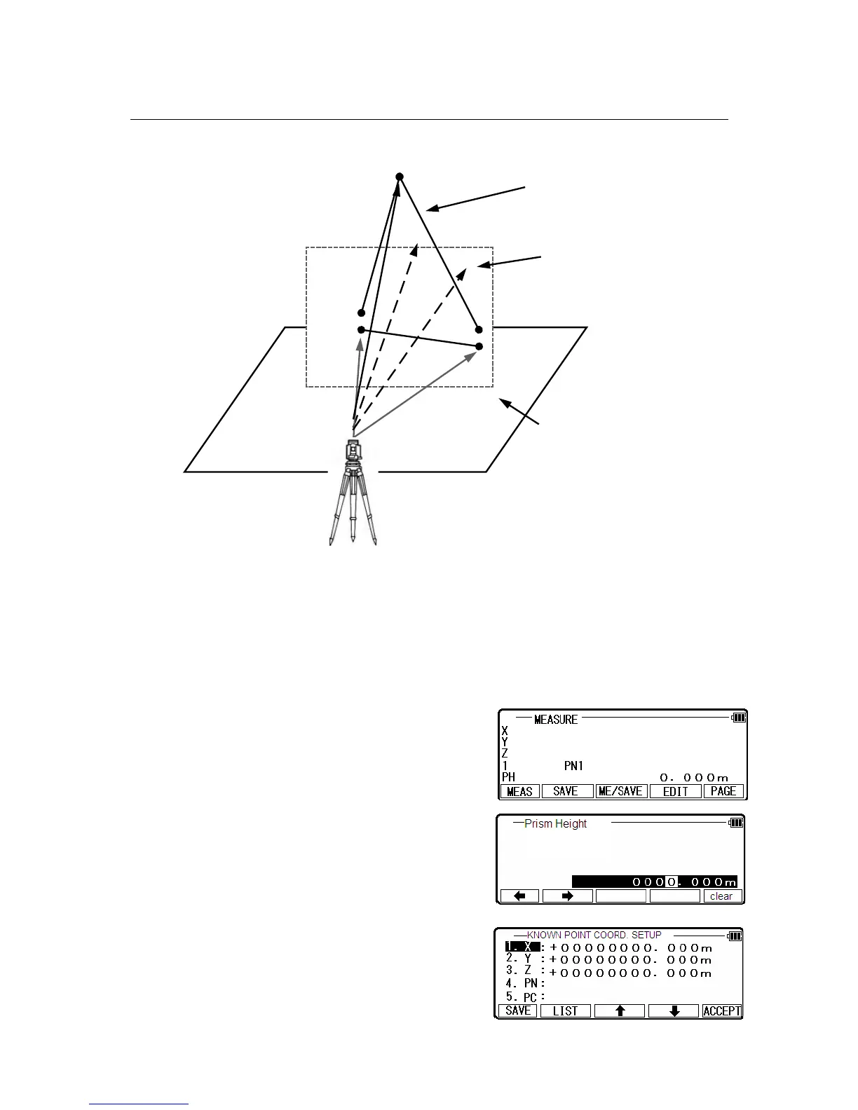
3.3. VPM
The Virtual plane includes the Vertical plane.
With VPM, the Coordinates on the vertical plane and virtual plane can be obtained by entering
the “Station Coordinates and Azimuth” and by measuring P1, P2 and P3.
Two points make a vertical plane and three points make a virtual plane.
You can measure the Point Coordinates of this virtual plane by aiming at your desired points.
Press [ENT] of the LinertecExpress screen to view the
“Measure” screen .
Press[F4] [Edit] to input the Prism Height
of the reference point.
Press [ENT] to enter“KNOWN POINT
COORD. SETUP”screen.
18
P1
P2
P3
Azimuth
Station
Coordinates
Vertical plane created
by 2 points
Coordinates of your aimed
point on the vertical plane
Virtual plane created by 3 points
 Loading...