10 | 4D-Nucleofector
®
Manual
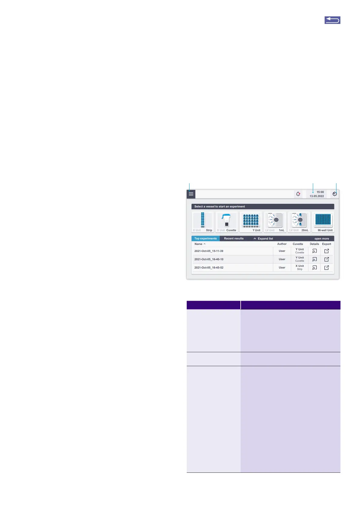
2.7.2 Operating software
The 4D-Nucleofector
®
System is operated via an 8-inch
touch screen display and is controlled by intuitive soft-
ware. Figure 2.4 and Table 2.2 will familiarize you with the
functions of the touch fields and the basic features of the
operating software.
Figure 2.4: Main screen (home screen) elements and general icons.
Table 2.2: Main menu and general commands or icons
Menu item Description
Accordion menu (1) Return to the main screen (home screen)
Experiment section – Search, impot and expot
of experiments
Results section – Search impot and expot of
results
Cell type section – Search for, create new and
edit existing cell type specific protocols
Time and date (2) Shows time and date (changes can be made in
the Settings menu)
Gear wheel icon (3)
menus
Select “Settings” to set the following instru-
ment parameters:
• Date and date format (select date and differ-
ent formats to display)
• Time and time format (setting time and
switching between 24 h and am/pm display)
• Display brightness (slide to adjust the bright-
ness)
• Volume or mute sound (slide to adjust
volume)
• Setting the fill mode for LV Unit use (for
details, see chapter 2.12.1.1)
If a functional unit is active, additional com-
mands are available:
• Open/close drawer
• Cleaning mode (opens the drawer to clean
the retainer)
• Version
• Shut down
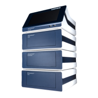
2.6 Set-up instructions
1. Unpack the components of the 4D-Nucleofector
®
System and check for damaged or missing components.
2. Stack the units with the Core Unit (containing the touch
screen) on top (Figure 2.2)
3. Connect the units (Figure 2.3) by using the interface
cables:
• Connect the interface outlet pot of the Core Unit (7)
with the interface inlet pot of the first functional unit
(X Y, or 96-well Unit; 8). Make sure that the cable is
securely attached and that the retaining screws on the
cable housing are screwed tightly into the pot.
• Futher functional units are added by connecting the
outlet (11) and the inlet pot (9) of adjacent units as
described above.
• Impotant: Plug in the interface terminator cap into the
outlet of the last unit (12).
4. Attach the power cord (5) to the power cord socket (4) at
the rear side of the Core Unit and plug it into an appro-
priate power outlet. Use only the power cord that comes
with the device.
5. Check all connections before turning on the system for
the first time.
Impotant note: If the device is not used for longer periods,
it will require occasional recharging to avoid battery dis-
charge and ensure functionality. To avoid a deep discharge
of the battery and loss of data, switch on the system at least
once a month.
The 4D-Nucleofector
®
System comes with default programs
and includes USB pots at the front and rear for software
updates and impot and expot of experiments and results.
2.7 General use instructions
This section gives an overview of the 4D-Nucleofector
®
System operating software. Details of the Nucleofection
®
Process can be found in the cell type-specific Optimized
Protocols (https://knowledge.lonza.com).
NOTE: All screenshots shown in this section refer to soft-
ware version 5.1.
2.7.1 Turning on the 4D-Nucleofector
®
System
Turn on the system using the main power switch at the rear
of the Core Unit. The blue LED at the front of the Core Unit
will be lit. Then press the power button at the front of the
Core Unit. The system will boot — this process may take a
few moments. Once the stat-up procedure is complete,
the 4D-Nucleofector
®
Graphical User Interface (touch
screen) will display the software’s main screen. The main
screen (home screen, Figure 2.4) displays all vessel types
that can be used with the respective functional units that
are attached to the Core Unit. It is possible to connect up to
three functional units with one 4D-Nucleofector
®
Core Unit.
In addition, at the bottom the recent results and the top
experiments used are shown.
321
Return to TOC