Chapter 11 Troubleshooting
11.4.2 Output circuit and corrective actions
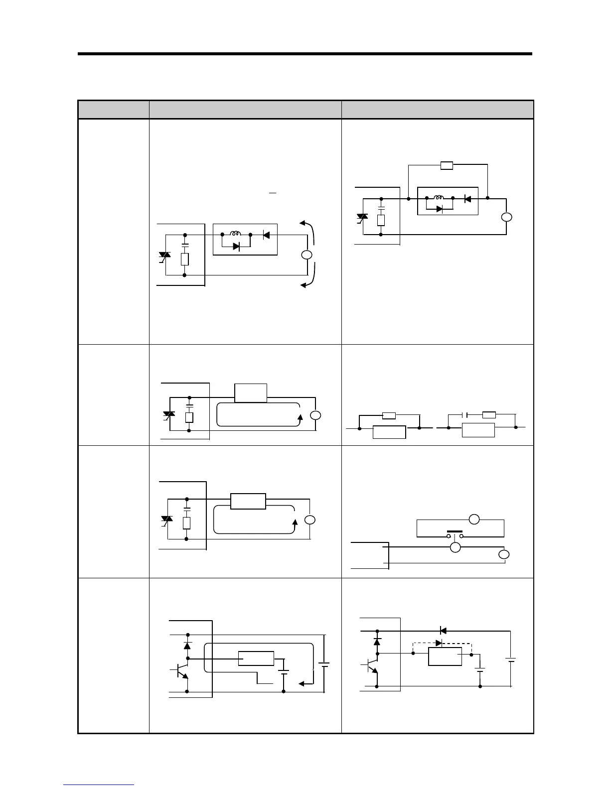
The following describes possible troubles with output circuits, as well as their corrective actions.
When the output
is off, excessive
voltage is
applied to the
load.
Load is half-wave rectified inside (in some
cases, it is true of a solenoid)
When the polarity of the power supply is as
②
the line voltage are applied across D. Max.
voltage is approx. 2√2.
*) If
a resistor is used in this way, it does not
pose a problem to the output element. But it may
make the performance of the diode (D), which is
built in the load, drop to cause problems.
Connect registers of tens to hundreds KΩ
across the load in parallel.
The load
doesn’t
turn off.
Leakage current by surge absorbing circuit,
which is connected to output element in parallel.
Connect C and R across the load, which are of
registers of tens KΩ. When the wiring distance
from the output module to t
he load is long, there
may be a leakage current due to the line
capacity.
When the load
is C-R type
timer, time
constant
fluctuates.
Leakage current by surge absorbing circuit,
which is connected to output element in parallel.
Drive the rel
ay using a contact and drive the
C-R type timer using the since contact.
Use other timer than the C−
ware rectified internal circuits
therefore, be cautious.
The load does
not turn off.
Sneak current due to the
power supplies.
E1<E2, sneaks. E1 is off (E2 is on), sneaks.
Use only one power supply.
Connect a sneak current prevention diode.
If the load is the relay, etc, connect a
counter-electromotive voltage absorbing code as