Chapter 7 Input/Output Specifications
7.2 Digital Input Specifications of Main Unit
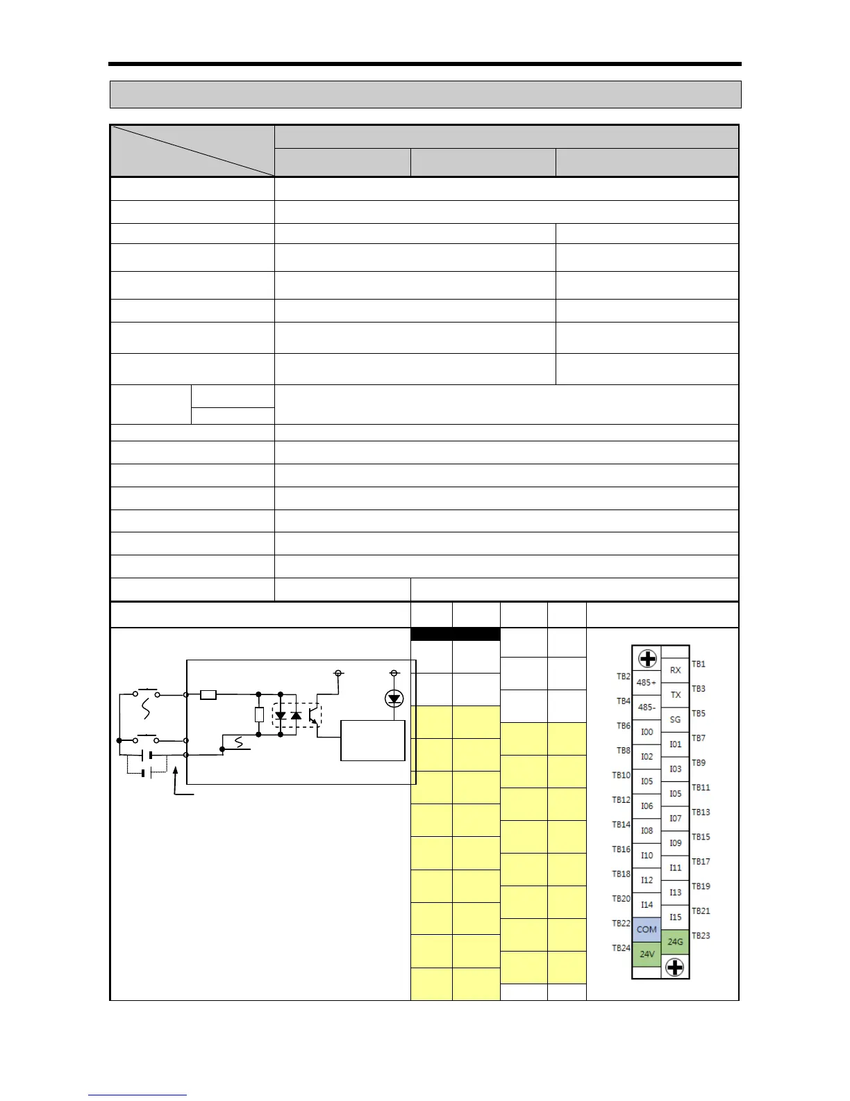
7.2.1 XEC-DR32H / XEC-DN32H input unit (Source/Sink type)
XEC-DR32H XEC-DR32H/D1
Input point 16 point
Insulation method Photo coupler insulation
Rated input voltage DC24V DC12/24V
Rated input current
About 4 ㎃ (point 0~7: About 10 ㎃)
About 5/10mA
(point 0~7: about 7/15mA)
Operation voltage range DC20.4~28.8V (ripple rate < 5%)
DC9.5~30V
(ripple rate < 5%)
On Voltage/Current
DC19V or higher / 3 ㎃ or higher DC9V or higher / 3 ㎃ or higher
Off Voltage/Current
DC6V or less / 1 ㎃ or less
Input resistance About 5.6 ㏀ (%IX0.0.0~%IX0.0.7: About 2.7 ㏀)
(%IX0.0.0
~%IX0.0.7: About 1.8
Response
time
Off → On
1/3/5/10/20/70/100 ㎳ (set by CPU parameter) Default: 3 ㎳
AC560Vrms / 3Cycle (altitude 2000m)
Insulation resistance
10 ㏁ or more by Mega ohmmeter
Common method 16 point / COM
Proper cable size 0.3 ㎟
Current consumption
200 ㎃ (when all point On)
Operation indicator Input On, LED On
External connection method 24 points connecting connector (M3 X 6 screw)
Weight 500g 600g
Circuit configuration
No. Contact No.
TB2 485+
TB3 TX
TB4 485-
TB5 SG
TB6 00
TB7 01
TB8 02
TB9 03
TB10 04
TB11 05
TB12 06
TB13 07
TB14 08
TB15 09
TB16 10
TB17 11
TB18 12
TB19 13
TB20 14
TB21 15
TB22 COM