Lynx NGT-9000s
Installation Manual
5. The WiFi interface must be configured using the MPC MAT WiFi interface prior to installation.
Refer to the Installation Checkout section (para. 3.3) for details.
6. When installing fail lamps in the cockpit, then amber colored lamps are required. Lamp power
should be connected to dimming bus or day/night switch. Label lamps as “Traffic Alert” (amber
lamp), “ADS-B Fail” (amber lamp), and “TIS-B No Coverage” (blue lamp) as applicable.
7. It is recommended that the installer perform the following wiring checks during installation:
• Check all wiring point-to-point for continuity before connecting components.
• Ensure voltages are not applied to signal wires.
• Inspect cables for correct connection.
8. Use the following information for interfacing compatible equipment. Additional information may be
found in the General Information section under Equipment Interfaces.
• Installations using the GMX 200 connect the Lynx NGT-9000s (TX pins 52 & 53) only.
2.3.2.1 Shielded Cable Preparation
• Use these instructions to prepare the Shielded Tefzel Wire (MIL27500) or equivalent for connection
to the 62 pin sub D connector.
• The crimp pins of the 62 pin connector are to be crimped to the wires.
• The Outer Jacket of the cable is to be removed for all cables on which the solder sleeve to be placed
for ground contact. The installer is to ensure that the outer jacket is removed on the cable for the
length of the cable inside the 62 pin connector backshell and can be around 1 to 1.5 inches from the
crimped pin side. Refer to Table 2-1 for the procedure on how to remove the jacket and insertion of
solder sleeve.
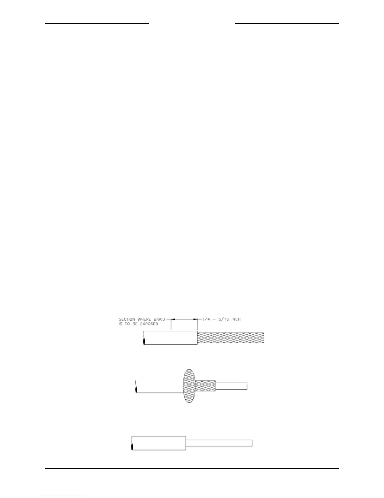
1. The cable can be stripped according to the following procedure designed to leave the shield braid
smooth and flat. The use of finger cots is recommended to prevent transfer of oils to the shield.
a. Score and remove the jacket as shown below:
b. Bunch the braid:
c. Trim the braid as close as possible to the jacket:
0040-17001-01 Installation Page 2-7
Revision A January 15, 2015
 Loading...