SETUP AND INSTALLATION 14000 OPERATOR MANUAL
4-26
Published 03-29-17, Control # 064-23 v2
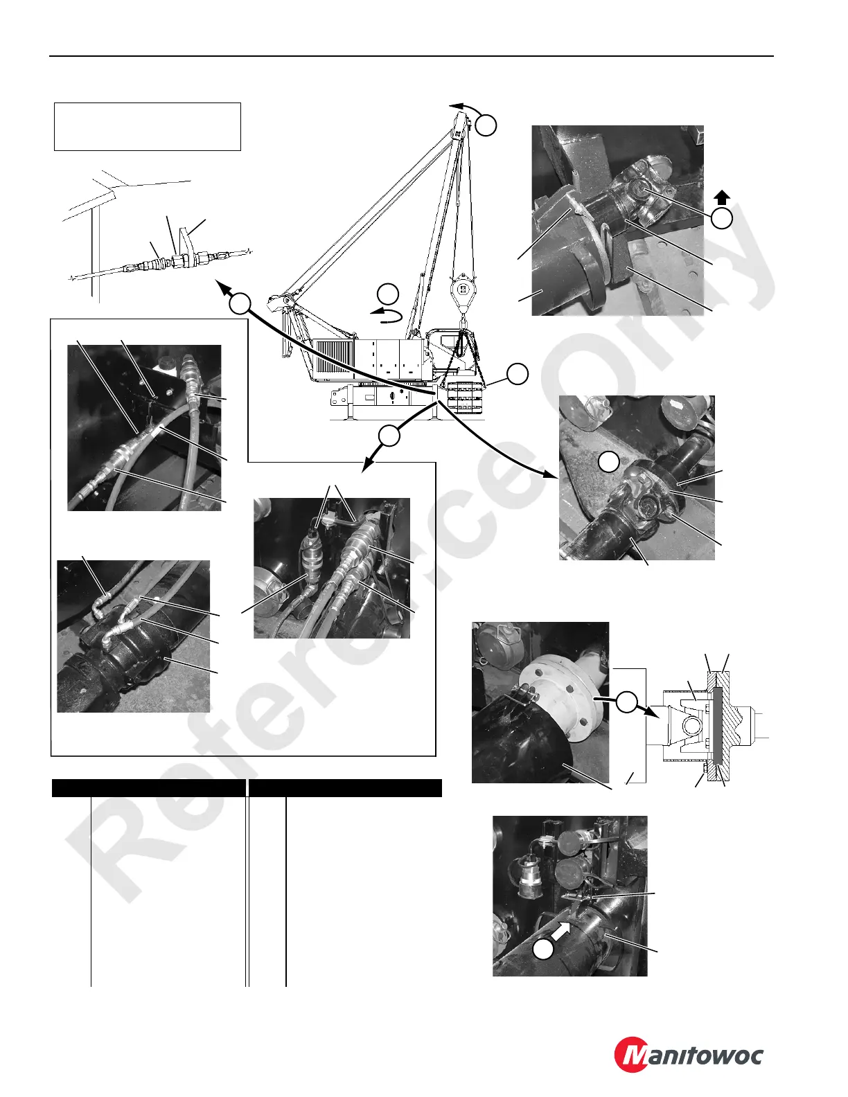
FIGURE 4-14
Item Description Item Description
1 Drive Shaft 11a Grease Line (from Crawler)
2 Bracket 11b Grease Line (from Pump)
3a Drive Shaft Flange 12 Bracket
3b Motor Flange 13 Travel Brake
4 Screw (4 each) 14 Hose (Case Drain)
5 Retainer 15 Hose (Case Drain)
6 Drive Shaft Spacer 16 Hose (Brake Release)
7 Motor Flange 17 Coupler (Relief Valve)
8 Screw (6 each) 18 Couplers (on Carbody)
9 Drive Shaft Guard 19 Bracket
10 Safety Pin
View A
11a
View H
Storage Position
P2416
P1455a
View C
P1456a
View D1
S/N 14001001, 14001002,
14001004 through 14001010
P1457a
View E
10
4
3a
1
9
10
View F
P2414
11b
12
14COM4185
View D2
S/N 14001003, 14001011
and Newer
P1456b
13
View G
Working Position
P2415
18
15
14
14
15
15
16
17
19
14
Items 14 through 19 and
Views F, G, and H Apply Only to
S/N 14001001, 14001002, and
14001004 through 14001010
9
2
9
1
3b
75
1
6
8
12
16
14COM4120
14
9
15
View B
16
16
14COM4118c
Circled Numbers Correspond to
INSTALL CRAWLERS
Procedure
10

 Loading...


