Manitowoc Published 03-29-17, Control # 064-23 v2 4-27
14000 OPERATOR MANUAL SETUP AND INSTALLATION
See Figure 4-14 for the following steps.
9. Unhook chain sling from crawler.
10. Lift crawler drive shaft (1, View C) off bracket (2).
11. For Serial Numbers (S/N) 14001001, 14001002, and
14001004 through 14001010 (see View D1):
a. Thoroughly clean ends of mating surfaces.
b. Extend drive shaft (1) and align holes in flanges (3a
and 3b).
c. Insert screws (4) and torque to 74 ft-lb (100 Nm).
12. For S/N 14001003, 14001011 and newer (see View D2):
a. Thoroughly clean ends of mating surfaces.
b. Extend drive shaft (1) and align drive shaft spacer
(6) with flange (7). The spacer (6) is screwed to the
drive shaft.
c. Align holes in retainer (5) with holes in flange (7).
d. Insert screws (8) and torque to 67 ft-lb (91 Nm).
13. Slide guard (9, View E) over drive shaft and pin guard to
carbody.
14. If equipped with automatic crawler lube system, connect
grease line (11a, View A) to (11b) at bracket (12) on
carbody.
15. For S/N 14001001, 14001002, and 14001004 through
14001010, connect travel brake hydraulic hoses in
following order:
a. Disconnect hydraulic hoses (15 and 16, View H)
from each other.
b. Disconnect hydraulic hose (14, View H) from
coupler (17).
c. Connect hydraulic hoses (14, 15, and 16, View G) to
couplers (18). Hoses can be connected one way
only.
16. Raise mast to 118° or higher, swing 180°, and repeat
steps 1 – 15 for other crawler.
17. Slowly rotate crawlers (travel forward and back) to
center treads on rollers.
18. Lower carbody until crawlers are on ground. Then fully
retract jacks.
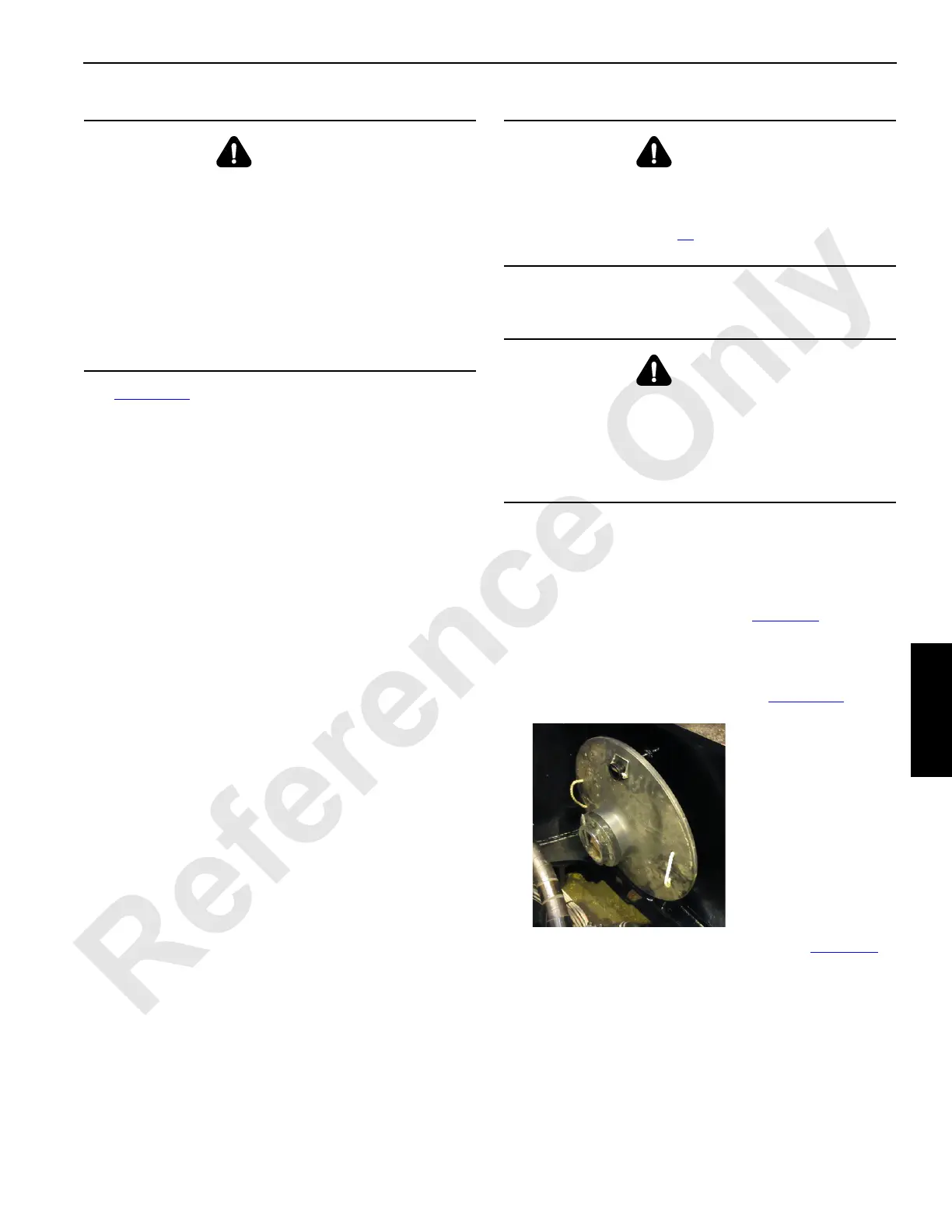
19. Remove jack pads (8, View E, Figure 4-8
) and store
(View D).
Store all but the right front jack pad on the ends of the
carbody. Store the right front jack pad on the right
inboard side of carbody as shown in Figure 4-15
.
20. Position each carbody jack as follows (see Figure 4-8
):
a. Remove hitch pin (7, View F).
b. Swing jack in (View E) for Series 1 and 2 only.
For Series 3, leave jacks out to allow for installation
of the carbody side counterweights.
c. Install hitch pin (7).
DANGER
Rotating Drive Shaft Hazard
Crawler drive shaft rotates at high speed. Prevent death
or serious injury:
• Make sure drive shaft is securely attached at both
ends
• Make sure guards are in place and securely attached
at both ends during operation
• Do not attempt to service drive shaft until crane has
been parked and engine stopped
DANGER
Tipping Hazard!
Prevent crane from tipping:
• Do not swing in step 16
until mast is raised to 118° or
higher
DANGER
Tipping Hazard!
Prevent crane from tipping:
• Do not allow assembly block to swing past inside
edges of carbody jacks while installing second
crawler or the crane will tip
FIGURE 4-15
Right Front Jack
Pad Stored

 Loading...


