Manitowoc Published 03-29-17, Control # 064-23 v2 4-61
14000 OPERATOR MANUAL SETUP AND INSTALLATION
8. Remove hitch pin (18, View D) and collar (19) from all
four connecting pins.
9. Store collars and hitch pins as shown in View C.
10. Attach three hooks from chain sling (20, View B) to lifting
links (21) on outboard side of desired crawler (23) and to
lifting lug (22) on inboard side of crawler.
11. Using crawler pins control (View G), retract crawler
connecting pins (25, View D) for crawler being removed.
NOTE: The connection between the crawler frame and
carbody can bind during operation. This binding will
make it extremely hard to lift the crawler away from
the carbody. To break the binding, perform step 12.
12. Break binding in connection between crawler and
carbody:
a. Install blocking (30, View H) snugly between ground
and both ends of crawler — under roller (30) at one
end and under tumbler at other end.
b. While one person operates carbody jacks, have two
assistants watch connections between crawler
frame and carbody (one each end).
c. Lower crawler onto blocking by slowly retracting
both carbody jacks next to crawler being removed.
d. STOP when assistants signal that both connections
have been broken between crawler frame and
carbody.
Retract jacks only enough to break binding. Do
not allow crawler to disengage carbody.
e. Extend jacks to level carbody, and remove blocking
from under crawler.
13. Slowly hoist, mast up, and swing as required to
disengage crawler hooks (26, View F) from fixed pins
(27) in carbody (28).
14. Place crawler on ground for storage or place it on trailer
(View E) for shipping.
15. Disconnect chain sling from crawler.
16. Securely attach crawler to trailer.
17. Raise mast to 118° or higher, swing 180°, and repeat
steps 10 – 16 for other crawler.
DANGER
Falling Load Hazard!
Prevent structural failure of components while handling
either crawler with mast:
• Make sure crane is level. Check level on front of
carbody. Adjust jacks as required
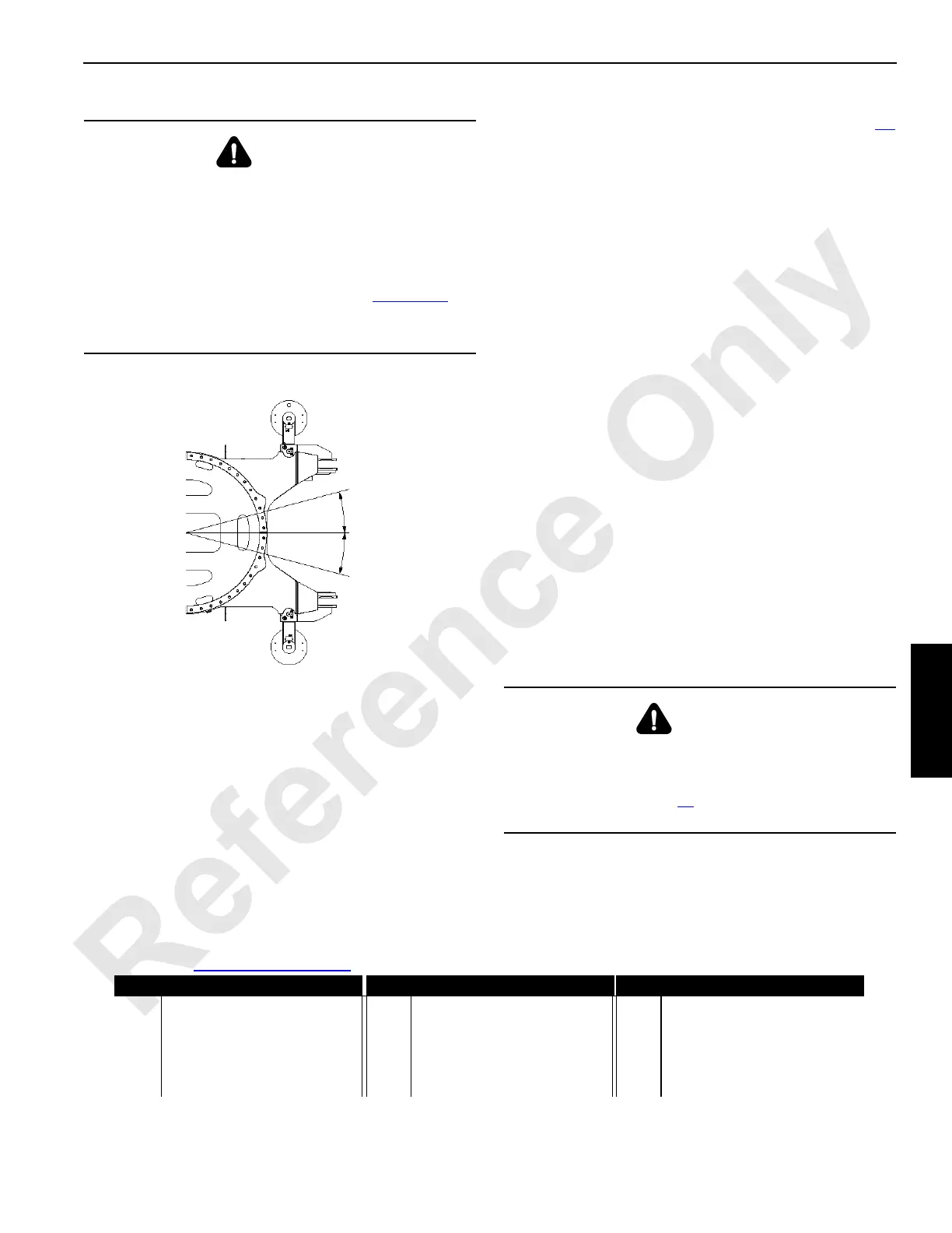
• Do not swing 15° either side of center (Figure 4-27
)
• Do not exceed lifting capacities given in Liftcrane
Mast Capacities Chart at end of this section
Swing Diagram
FIGURE 4-27
15°
15°
Centerline
14COM4119
DANGER
Tipping Hazard!
Prevent crane from tipping:
• Do not swing in step 17
until mast is raised to 118° or
higher
Legend for FIGURE 4-26 continued
Item Description Item Description Item Description
18 Hitch Pin with Hair Pin Cotter 23 Crawler 27 Fixed Pin
19 Collar 24a Left Crawler Pins Control 28 Carbody
20 Chain Sling (4 Leg) 24b Right Crawler Pins Control 29 Roller or Tumbler
21 Lifting Link 25 Crawler Connecting Pin 30 Blocking
22 Lifting Lug 26 Hook

 Loading...


