OPERATING CONTROLS AND PROCEDURES 14000 OPERATOR MANUAL
3-24
Published 03-29-17, Control # 064-23
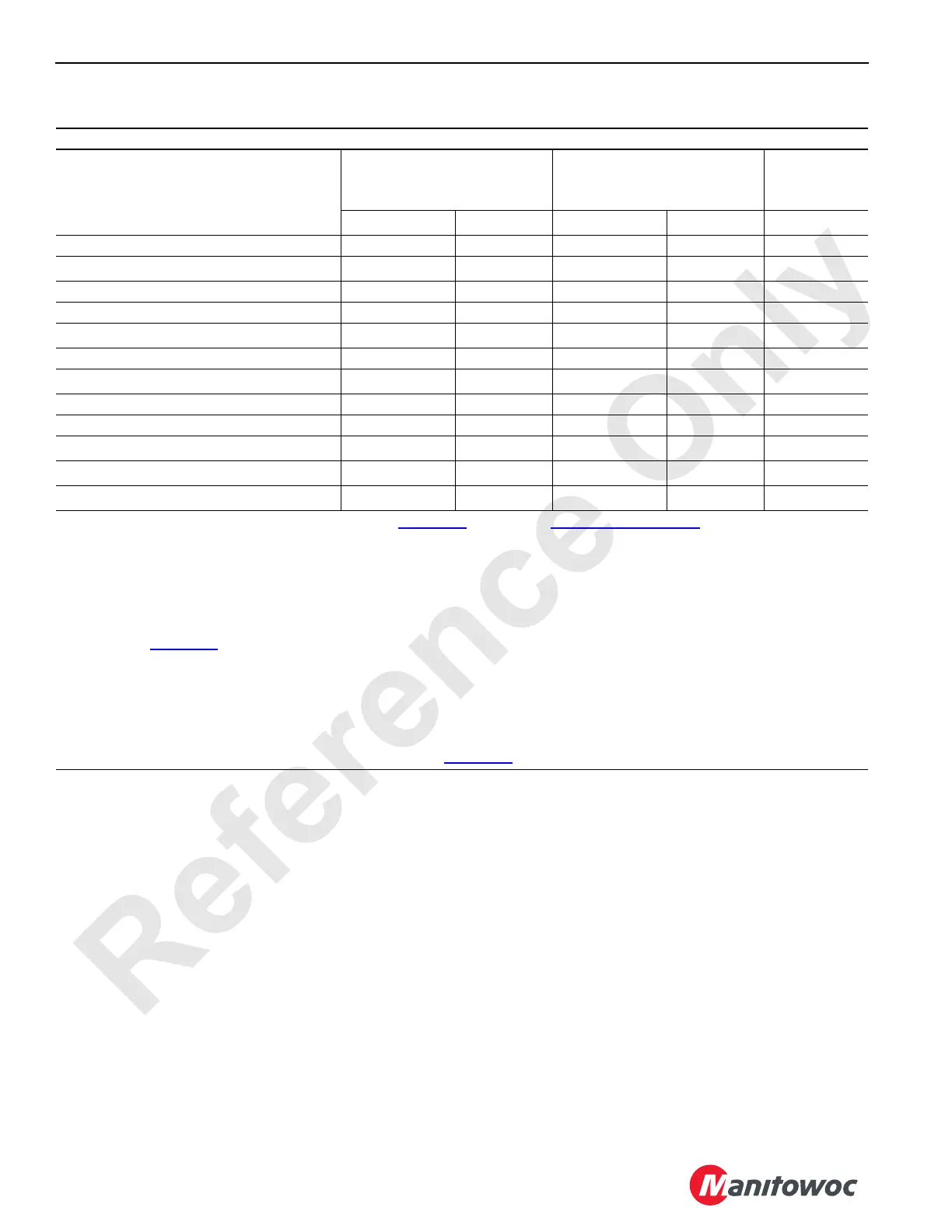
Table 3-3 Bypassable Limit Identification Current Production Model 14000
NOTE: Cranes meeting 2010 European requirements are equipped an RCI/RCL External Override Switch located outside
the operator’s cab (see Rated Capacity Indicator/Limiter Operation Manual).
This Table Applies to Cranes Without Luffing Jib Limit Bypass Switch (D5)
Limit
Limit Bypass Switch (D4)
(momentary key switch)
Limit Bypass Switch (D4)
(momentary key switch)
Luffing Jib Setup Mode On
1
External
Override
Switch
2
Non-CE
CE
3
Non-CE
CE
3
CE
3
Boom Up No No No No No
Block Up (each drum) Yes
Yes
6
Yes Yes No
Minimum Bail (each drum) Yes No No No No
Luffing Jib Maximum Up 1 Yes No Yes Yes No
Luffing Jib Maximum Up 2 Yes No
Yes
4
Yes
4
No
Luffing Jib Maximum Down 1 Yes No Yes Yes No
Luffing Jib Maximum Down 2
Yes
5
No
Yes
5
No No
Mast Too Far Forward No No No No No
Gantry Down Yes Yes No No No
Boom Limiter
8
Yes Yes No No No
Swing Limiter
8
No No No No No
Rated Capacity Indicator/Limiter Yes
Yes
6
Yes
Yes
6
Yes
7
1
Use only for rigging. See procedure described on Page 3-44 for enabling Luffing Jib Setup Mode
2
See Rated Capacity Indicator/Limiter Operation Manual
3
CE = Cranes that comply with 2010 European requirements (see NOTE below)
4
Only when boom is below 50°
5
When this limit is contacted, operation will stop and you will not be able to continue lowering luffing jib. See Luffing Jib Max
Down 2 on Page 3-31
for detailed instructions
6
Only if boom or luffing jib is below allowable angle given in Capacity Chart (while raising or lowering boom and luffing jib
from or to ground level)
7
When the external bypass is in override, the speed of the crane functions are limited to 15% of their maximum speed for
movements that increase load
8
Cranes equipped with boom or swing motion limiter (see Page 3-60 for procedure)