Grove Published 7-23-2020, Control # 668-02 4-35
GRT9165 OPERATOR MANUAL OPERATING PROCEDURES
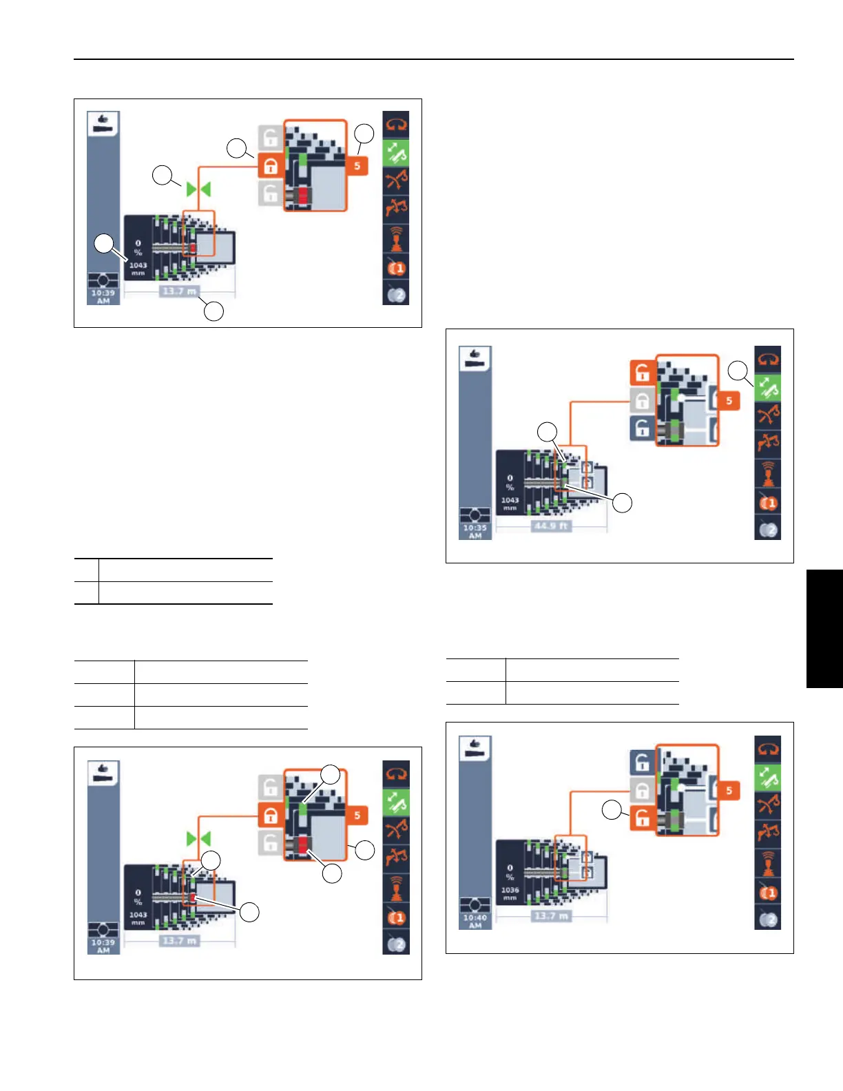
Position of the Telescoping Cylinder
If the telescoping cylinder is near a locking point:
• The display (3, Figure 4-19) shows the corresponding
telescopic section, e.g. telescopic section 5.
• The display (4, Figure 4-19) shows one or two arrows,
depending on the distance to the locking point. The
display (4) shows two arrows and the display (5) lock
symbol appears orange when the telescope cylinder is
at the locking point.
Position of the Locking Pins
The current positions of the locking pins are (Figure 4-20):
The area (3) shows an enlarged cut-out.
The current settings are shown in different colors.
Unlocking the Telescoping Cylinder
Unlocking the telescoping cylinder is required for the
telescoping cylinder to be moved separately (without the
telescopic section).
The telescoping cylinder and the telescopic section cannot
be unlocked simultaneously.
Prerequisites
Telescoping function enabled – symbol (3, Figure 4-21)
green
Telescoping cylinder locked – symbol (2) green
Telescopic section locked – symbol (1) green
Unlock
1. Select the symbol (1, Figure 4-22).
2. Confirm the selection – the telescope cylinder locking
pins (2, Figure 4-23) will retract.
1 on the telescopic section
2 on the telescoping cylinder
Red: Unlocked
Green: Locked
Yellow: Intermediate position
Yellow: Intermediate position
Red: Unlocked

 Loading...


