Grove Published 7-23-2020, Control # 668-02 4-43
GRT9165 OPERATOR MANUAL OPERATING PROCEDURES
section will be locked at this pinning location. If the
telescope controller is not used, then the boom section
can remain at that location and not locked (note that the
boom section could also now be retracted and the boom
fully retracted, if desired, without changing the target tele
picture / requested final boom configuration).
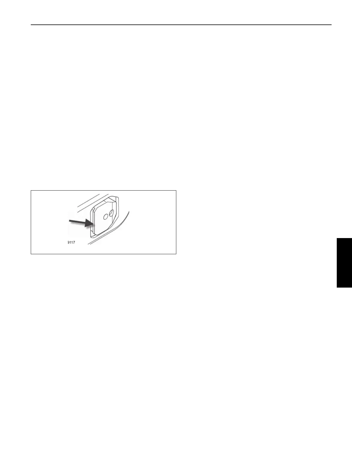
• Assuming that the boom section is requested to be
locked, it is important to know that there are a few
phases to the automated motion to lock the boom
section. In particular, Figure 4-41 shows that there is a
“lip” on the boom section pins (pointed to by the arrow in
figure). The first phase for boom section locking is to
release/extend the pins into the hole/cutout in the
encompassing boom section. If this is successful, then
there is a second phase of automated motion to set
down the boom section on the proper flat surface of the
pins that is next to the lip. In a final phase, the pin is
confirmed to be engaged and the boom section locked
by the control system commanding the telescoping
cylinder to retract and then checking for no boom
motion. If there is no motion, then it is confirmed as
locked.
• After the boom section is locked, the left AND right
arrows are shown blinking. This indicates to the operator
that the boom can be retracted or extended, and that in
either case, there will be automated motions and to be
aware that it will take some time (the blinking is an
indication to the operator that this time will be needed).
• Assuming the boom is to continue to be extended, the
operator would use the telescope controller in the
extend direction for at least 1 second. This is interpreted
as the indication to change to extending the next boom
section (T4 in this example). Therefore, the telescoping
cylinder will automatically unlock from the T5 boom
section, retract to the T4 boom section, lock to the T4
boom section, and then unlock the T4 boom section.
• When the T4 boom section is unlocked, the left and right
telescoping direction arrows will appear again (as is
shown in Figure 4-37).
• The operator can telescope the next boom section (T4).
• The T4 boom section operating process is the same as
for the T5 boom section described above. When the T4
boom section is at its 100% pinning location, then it can
be locked in the same manner (using the extend
direction of the telescope controller for at least 1 second
when the right arrow is blinking).
• With the T4 boom section at its requested final location,
only the left arrow would be blinking. This is indicating
that it is impossible to telescope the boom any further
(the boom has arrived at its final configuration as
requested).
The following steps would be expected for fully retracting the
boom in Semi-auto Mode:
• DO NOT ENTER a new boom configuration or “target
tele picture” (such as 0-0-0-0-0) just to fully retract the
boom.
• At any point in the boom extending procedure
(described above), when the left arrow is shown, the
telescope controller can be used in the retract direction
to retract the boom (partially or fully).
• The operator can use the telescope controller in the
retract direction for at least 1 second, and then the
automated motion to unlock the boom section (T4 in the
example) will start. It is important to know that there are
two phases for unlocking a boom section. As mentioned
previously, and shown in Figure 4-41, there is a lip on
the boom section pins. Therefore, the first phase of the
automated motion is to lift up the boom section to have
clearance from this lip. After the lift up is completed, then
the pins are retracted. The boom section is now able to
be retracted.
• The operator can retract the first boom section to move
(T4). But note that the retract and extend arrows are
again shown. It is possible for the operator to change
direction once again and return to extending the boom, if
desired.
• Assuming the boom is to be fully retracted, the operator
would retract the first section. The boom section will
slow down near the 0% pinning location. If the operator
continues to retract the boom section to the 0% pinning
location, the boom motion stops. The left arrow is shown
blinking.
• The operator can command the retract direction for at
least 1 second, and then the boom section will lock at
0%.
• The left and right arrows would be shown blinking.
• The operator can continue to command the retract
direction for at least 1 second, and then the telescoping
cylinder will automatically unlock from the boom section,
extend to the next boom section to be retracted, and lock
to that boom section. Then the automated motion to
unlock the boom section will be used (now for boom
section T5 in this example). When unlocked, the left and
right arrows will appear again.

 Loading...


