FIGURE 4-95
10085-36
1 2 3
4 5 6 7
8
9
10
14
11
12
13
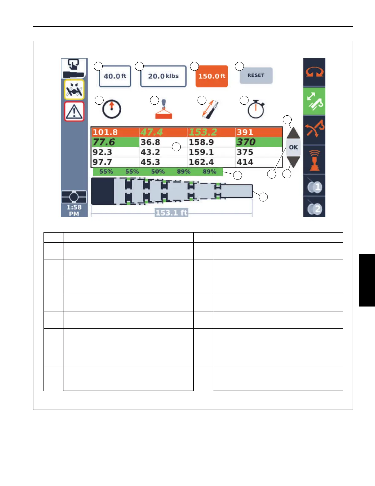
Item Description Item Description
1 Lift plan radius entry box 8
Table of possible boom configurations (“tele
pictures”) that meet the lift plan criteria.
2 Lift plan hook load entry box 9
For the row in the table that is highlighted, this is
the boom configuration (“tele picture”).
3 Lift plan boom length entry box 10
For the row in the table that is highlighted, this is
a schematic view of the boom configuration.
4
Symbol indicating radius for first column of the
table.
11
Up arrow, when selected and select Enter, the
highlighted row moves up in the table.
5
Symbol indicating hook load for second column
of the table.
12
Down arrow, when selected and select Enter,
the highlighted row moves down in the table.
6
Symbol indicating boom length for third column
of the table.
13
OK button; when selected and select Enter, the
highlighted row's boom configuration is
accepted and sent to the Semi-automatic mode
screen, and the boom commences to attempt to
use this boom configuration.
7
Symbol indicating approximate time (in
seconds) for boom configuration (“tele pictures”)
to be completed.
14
Reset option; when selected and select Enter,
the lift plan entry values are set to 0 and boom
configurations cleared.

 Loading...


