OPERATING PROCEDURES GRT9165 OPERATOR MANUAL
4-120 Published 7-23-2020, Control # 668-02
Using the Left Arrow and Right Arrow Function keys on the
Navigation Control Pad (4, Figure 4-69) or the Jog Dial
(5, Figure 4-70) changes the Icon highlighted on the screen.
As the arrow keys are pressed, the highlight will move
between the Icons, with the color orange typically meaning
that the Icon is selected and can be affected by subsequent
actions. In Figure 4-117, you will see that the highlighted Icon
in orange for the Enable/Disable Switch Symbol for the
maximum boom angle is selected since it has the orange
color highlighting.Table 4-9 lists the WRL Limitation Screen
Symbols.
NOTE: The Boom Angle can be “typed in” or set by a boom
position.
Setting the Boom Angle Limitation Menu
The Boom Angle Limitation Menu allows the operator to set
the upper and/or lower limits for the boom to operate within.
Setting the Boom Up Angle Limitation by Crane
Position
To set parameters and enable the Boom Up Angle Limitation,
the following steps can be used:
1. Set the RDM screen parameters first. Refer to Using the
Rated Capacity Limiter Display Module (RDM), page
4-159.
2. Using the Jog Dial (5, Figure 4-70), go to the ODM Main
Menu Screen (Figure 4-83). Go to the Working Range
Limiter (WRL) Group Menu Icon (3, Figure 4-115) by
using the Arrow keys (4, Figure 4-69) or the Jog Dial (5),
(Figure 4-70).
3. Select the Boom Angle Limitation Menu Screen
(3, Figure 4-115). NOTE: The Boom Up Limitation
Screen (8, Figure 4-117) Icon is shown on the top left
side of the ODM screen.
4. Move the Boom to the desired position. This position will
indicate the boom angle current value A (2) position.
5. Enable the Limitation by using the Jog Dial
(5, Figure 4-70), or the Arrow Keys (4, Figure 4-69) to
move and select the Enable/Disable Switch Symbol
ON/Off (1, Figure 4-117). NOTE: The Switch
(1, Figure 4-117) is a toggle switch. Click OK
(5, Figure 4-69), or the Jog Dial (5, Figure 4-70) to
enable the switch.
6. Use the Jog Dial (5, Figure 4-70) or the Arrow Keys
(4, Figure 4-69) and move to the Limitation Value
(2, Figure 4-117). Click OK to set the current value
Limitation A (2, Figure 4-117) position.
NOTE: The current value in Limitation A (2) will
automatically populate in the value for Limitation A
(3).
NOTE: The boom is now at the limitation, so alarms will
sound. The boom can now be moved away from
the current boom angle to cease the alarm.
Setting the Boom Down Limitation by Crane Position
To set parameters and enable the Lower Boom Angle
Limitation, the following steps can be used:
1. Set the RDM screen parameters first. Refer to Using the
Rated Capacity Limiter Display Module (RDM), page
4-159.
2. Using the Jog Dial (5, Figure 4-70), go to the ODM Main
Menu Screen (Figure 4-83). Go to the Working Range
Limiter (WRL) Group Menu Icon (3, Figure 4-115) by
using the Arrow keys (4, Figure 4-69) or the Jog Dial
(5, Figure 4-70).
3. Select the Boom Angle Limitation Menu
(3, Figure 4-115). NOTE: The Boom Angle Limitation
Icon (8, Figure 4-117) is shown on the top left side of the
ODM screen.
4. Move the Boom to the desired position. This position will
indicate the boom angle current value B (5) position.
5. Enable the Lower Boom Limitation Angle by using the
Jog Dial (5, Figure 4-70), or the Arrow Keys
(4, Figure 4-69) to move and select the Enable/Disable
Switch Symbol ON/Off (4, Figure 4-117). NOTE: The
Switch (4, Figure 4-117) is a toggle switch. Click OK
(5, Figure 4-69), or the Jog Dial (5, Figure 4-70) to
enable the switch.
6. Use the Jog Dial (5, Figure 4-70), or the Arrow Keys
(4, Figure 4-69) and move to the Limitation Value
(5, Figure 4-117). Click OK to set the current value
Lower Boom Angle Limitation B (5, Figure 4-117)
position.
NOTE: The current lower boom angle Limitation B (5) will
automatically populate in the value for Limitation B
(6).
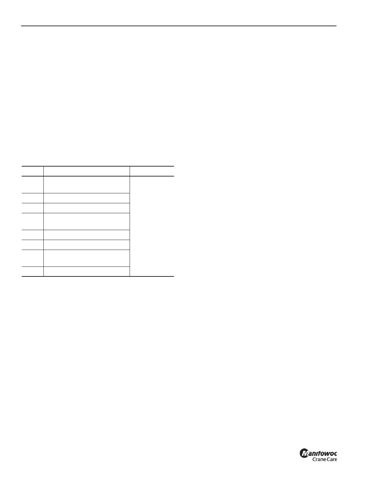
Item Description Refer to
1
Upper A (Maximum Boom
Angle) Limit ON/OFF
Figure 4-117
2 Current Boom Angle
3 Maximum Boom Angle Limit
4
Lower B (Minimum Boom
Angle) Limit ON/OFF
5 Current Boom Angle
6 Minimum Boom Angle Limit
7
Audible Alert or Lock-out
Symbol
8 Boom Angle Limitation Icon

 Loading...


