SET-UP AND INSTALLATION MLC650 VPC-MAX™ OPERATOR MANUAL
4-66
Published 04-06-18, Control # 231-14
Installing the Boom Assembly
See Figure 4-59 for the following procedure.
NOTE: A minimum of Series 1 counterweight is required to
install the partial boom with the fixed mast.
1. Make sure the live mast arms are in the stored position.
See Section 4 of the Crane Operator Manual for
instructions.
2. Reconfigure the rated capacity limiter (RCL)/rated
capacity indicator (RCI) to the fixed mast handling
configuration. See the RCL/RCI Operator Manual for
instructions.
3. While lifting the equalizer off the ground, raise the fixed
mast until the top is approximately 3 m (10 ft) off the
ground and reinstall the rope guard (6, Figure 4-58 on
page 4-65.
4. Raise the fixed mast to the operating range specified in
Figure 4-59
.
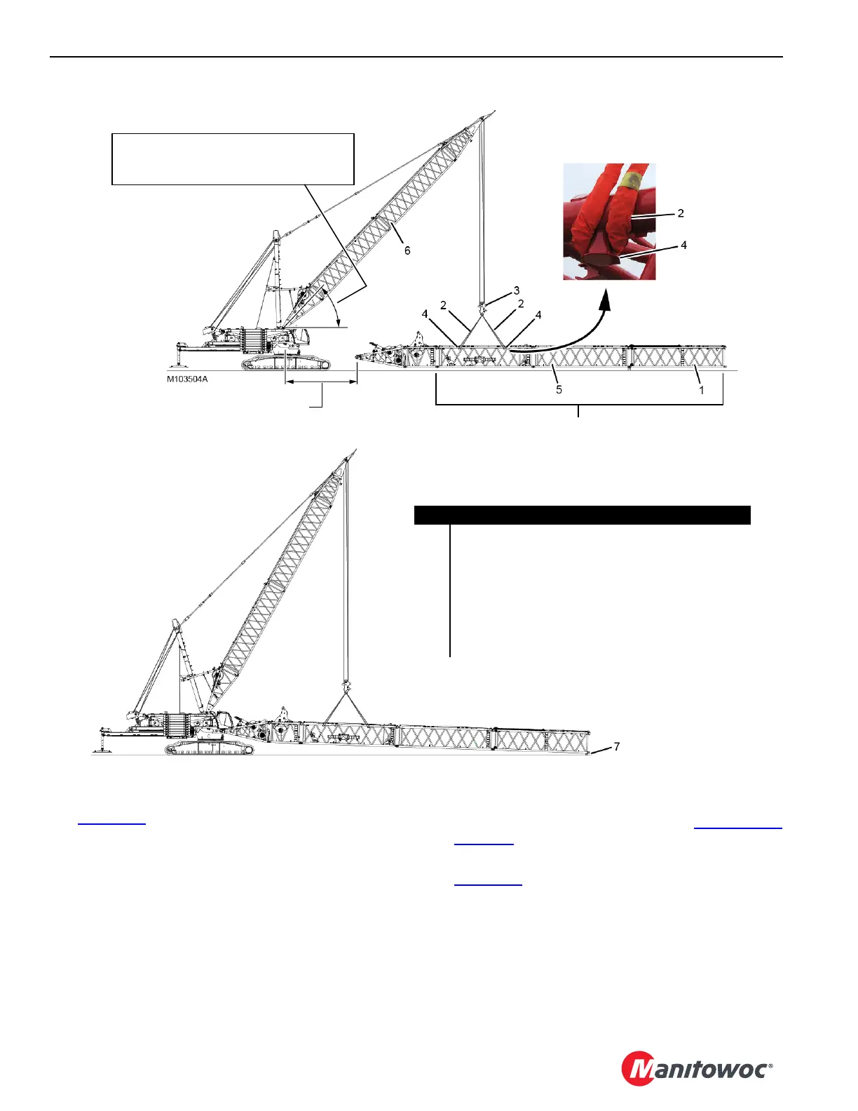
5. Assemble the partial boom up to the equalizer insert (1,
View A).
• See Section 4 of the Crane Operator Manual for
boom assembly instructions.
• Either an assist crane or the fixed mast can be used
to assemble the partial boom.
View B
View A
Item Description
1 Equalizer Insert
2 SL 6 Sling – 5 m (16.40 ft), 31 751 kg (70,000 lb) (qty 4)
3 Equalizer
4 Lifting Lug (qty 4)
512M Insert
6Fixed Mast
7 Blocking – 610 mm (24 in) high
FIGURE 4-59
NOTE: Depending on Boom Rigging in use, these can be
either #680 boom sections or #685-680 boom sections.
Operating Range:
- 39.7-64.5° for Standard Boom (#680)
- 46.8-64.5° for Wide Boom (#685-680)
11.9 m (39 ft 0.5 in) for #680 Boom
8.2 m (26 ft 11 in) for #685-680 Boom