Manitowoc Published 04-06-18, Control # 231-14 6-1
MLC650 VPC-MAX™ OPERATOR MANUAL MAINTENANCE
SECTION 6
MAINTENANCE
This section contains maintenance and adjustment
instructions for the limit devices used with the VPC-MAX
attachment.
For maintenance and inspection of the following
components, see the Service Manual supplied with your
crane:
• Straps
• Wire Rope
• Load Block and Hook-and-Weight Ball
• Boom and Jib
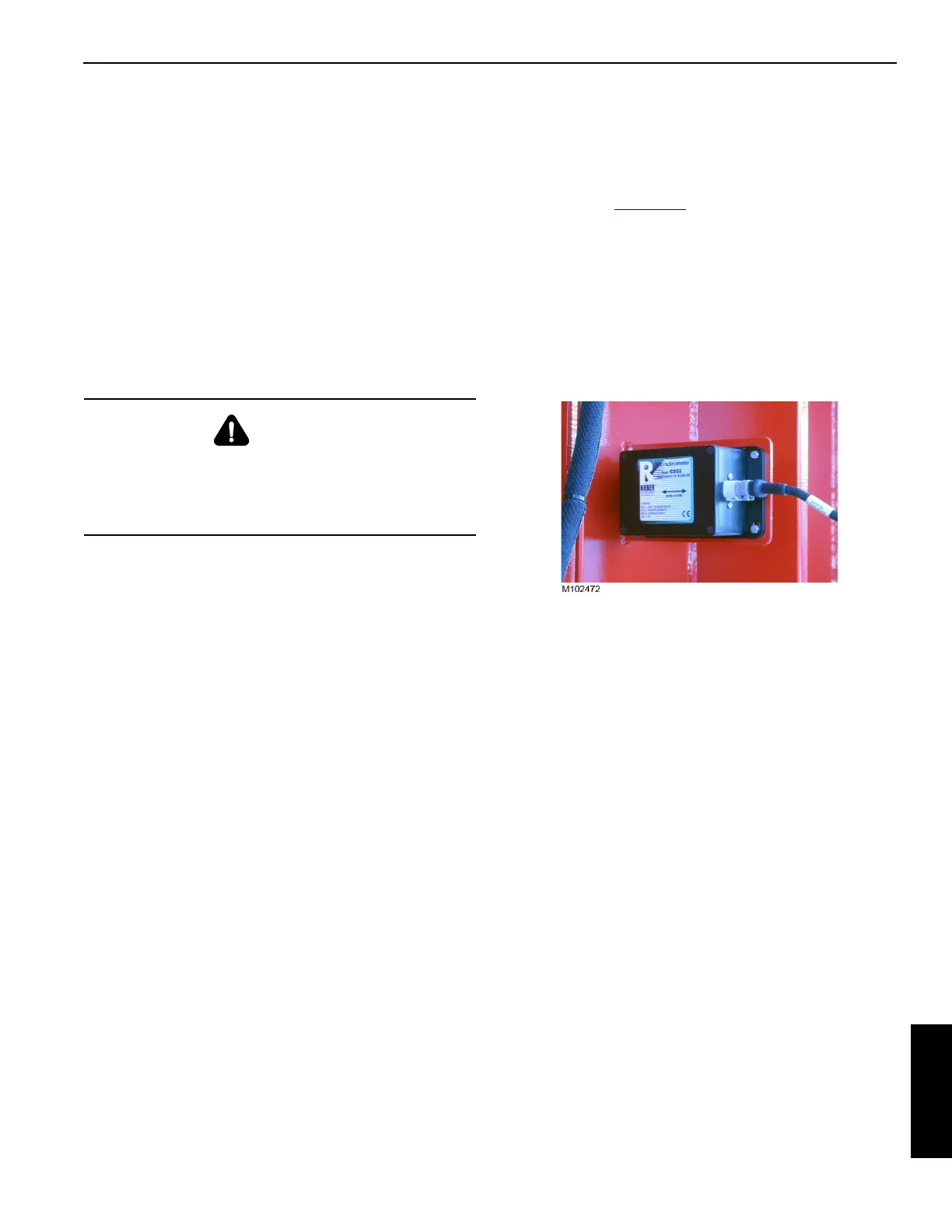
ANGLE SENSORS
Angle sensors (Figure 6-1) are mounted at the following
locations:
• Boom Top
• Boom Butt
• Luffing Jib Top
• Luffing Jib Butt
The sensors are calibrated in the RCL/RCI display and do
not require adjustment.
WARNING
Avoid Injury
Read, understand, and follow the safe maintenance
practices in Section 1 of the Service Manual provided with
your MLC650.