MAINTENANCE MLC650 VPC-MAX™ OPERATOR MANUAL
6-10
Published 04-06-18, Control # 231-14
Adjusting the VPC-MAX Trolley Roller
Backlash
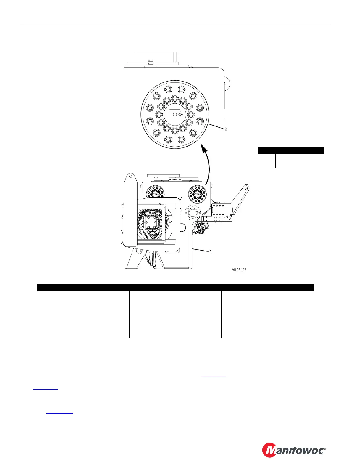
See Figure 6-8 for the following procedure.
Initially position the VPC-MAX trolley (1) roller assembly (2)
so that the slot is horizontal and above the roller axis as
shown in Figure 6-8
. The roller assembly shaft has 2 mm
(0.08 in) of eccentricity. It is possible to adjust the rack and
pinion backlash by rotating the shaft in the bore. See the
table in Figure 6-8
for permissible front and rear adjustment
combinations and the resulting change in backlash. To
decrease the backlash, rotate the shaft counterclockwise. To
increase the backlash, rotate the shaft clockwise.
Corresponding increases in backlash will result. Adjust
equally side to side.
Item Description
1 VPC-MAX Trolley
2 Roller Assembly
Front Shaft Rotation Angle CCW Rear Shaft Rotation Angle CCW Resulting Decrease in Backlash
0° 0° 0 Initial Position
0° 30° 0,42 mm (0.02 in)
30° 30° 0,85 mm (0.03 in)
30° 60° 1,15 mm (0.05 in)
60° 60° 1,46 mm (0.057 in)
60° 90° 1,58 mm (0.06 in)
90° 90° 1,69 mm (0.07 in)
FIGURE 6-8