Manitowoc Published 04-06-18, Control # 231-14 4-23
MLC650 VPC-MAX™ OPERATOR MANUAL SET-UP AND INSTALLATION
Attaching the Connecting Link
See Figure 4-23 for the following procedure.
1. Remove the locking pin (1) and retaining pin (2) from the
connecting link (3).
2. Remove the connecting link from the stored position in
the rotating bed bracket (4).
3. Adjust the slide and/or tray position to align the
connecting link with the actuator bracket (5).
4. Install the retaining pin and hair pin cotter to secure the
connecting link in the working position in the actuator
bracket.
Installing the Large Main Stop Blocks
1. Drive the actuator forward to a position to allow for large
main stop block installation.
2. Install the large main stop blocks by reversing the
removal procedure. See "Removing the Large Main
Stop Blocks" on page 4-15.
3. Detach the actuator from the assist crane.
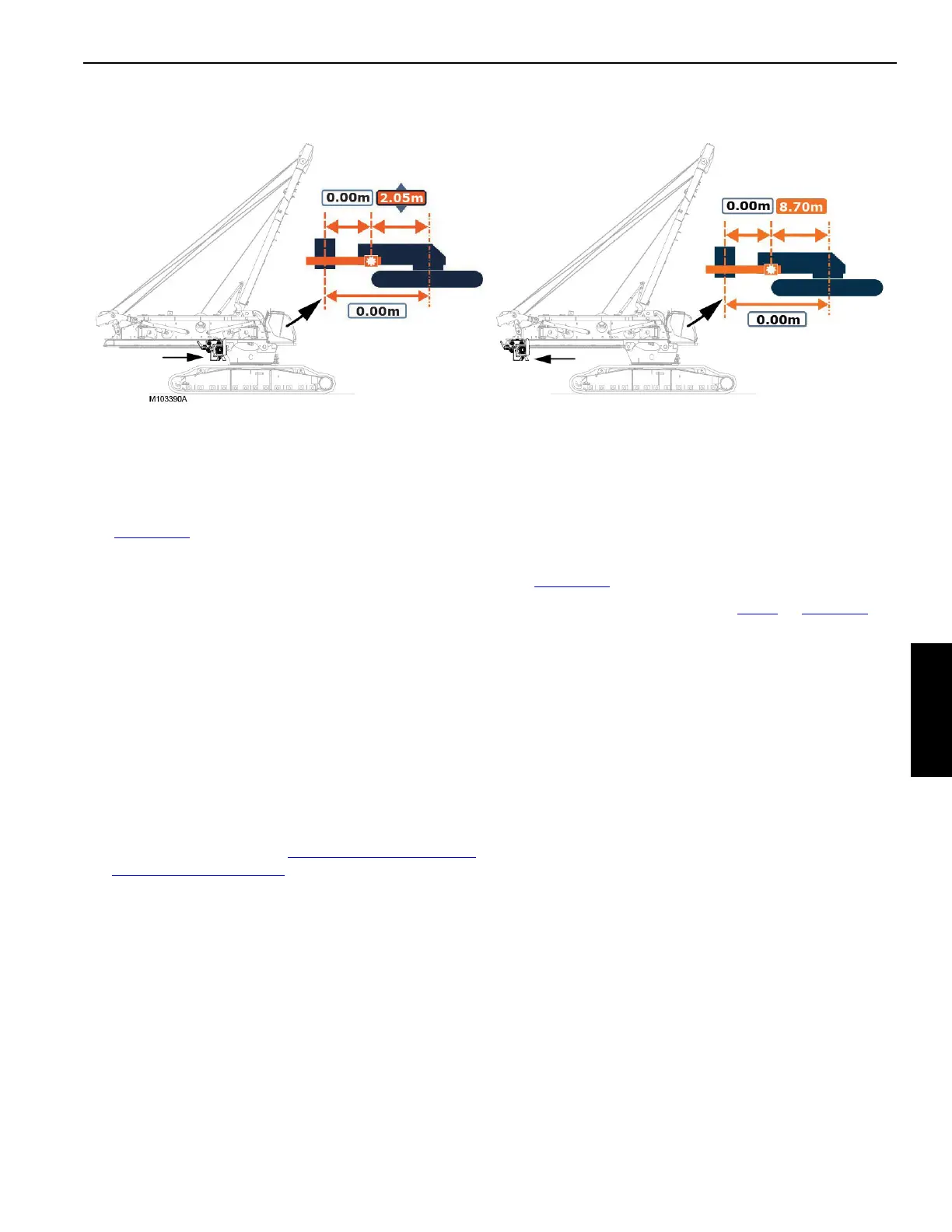
Checking Limits and Calibrating the VPC-MAX
Actuator
See Figure 4-23 for the following procedure.
1. Adjust the wear plate scrapers (step 2
on page 4-14).
2. Using the remote control, drive the actuator all the way
forward on the rotating bed rails (View A).
3. Verify that the actuator in and out limit switches are
operating properly.
See Section 6 of this manual for detailed instructions.
4. Calibrate the actuator in the VPC-MAX Calibration
Screen of the Main Display.
See the Main Display Operation Manual for detailed
instructions under the topic VPC-MAX Calibration at
Installation.
5. Once calibrated, drive the actuator rearward until it is at
8.70 m as indicted in the calibration screen (View B).
FIGURE 4-24
View A
Actuator Calibration Position
View B
Beam Installation Position